Radar apparatus and interference detection method

a radar and interference detection technology, applied in the direction of reradiation, measurement devices, instruments, etc., can solve the problems of inability to accurately detect bearings and the like, complicated computation needs to be carried out in the radar apparatus, and inability to detect bearings or the like accurately, etc., to achieve accurate interference detection without increasing throughput and simple configurations

Inactive Publication Date: 2007-07-26
FUJITSU GENERAL LTD +1
View PDF2 Cites 45 Cited by
  • Summary
  • Abstract
  • Description
  • Claims
  • Application Information

AI Technical Summary

Benefits of technology

[0026] According to the present invention, a radar apparatus and interference detection method that have simple con

Problems solved by technology

In such the radar apparatus, interference may occur with, for example, an oncoming vehicle equipped with a different radar apparatus, wherein a transmission wave of the different radar apparatus cannot be distinguished (separated) from a reflected wave, which is obtained when the transmission wave of the former radar apparatus is reflected on a target, and thereby erroneous detection o

Method used


Image

  • Radar apparatus and interference detection method
  • Radar apparatus and interference detection method
  • Radar apparatus and interference detection method

Examples


embodiment 1

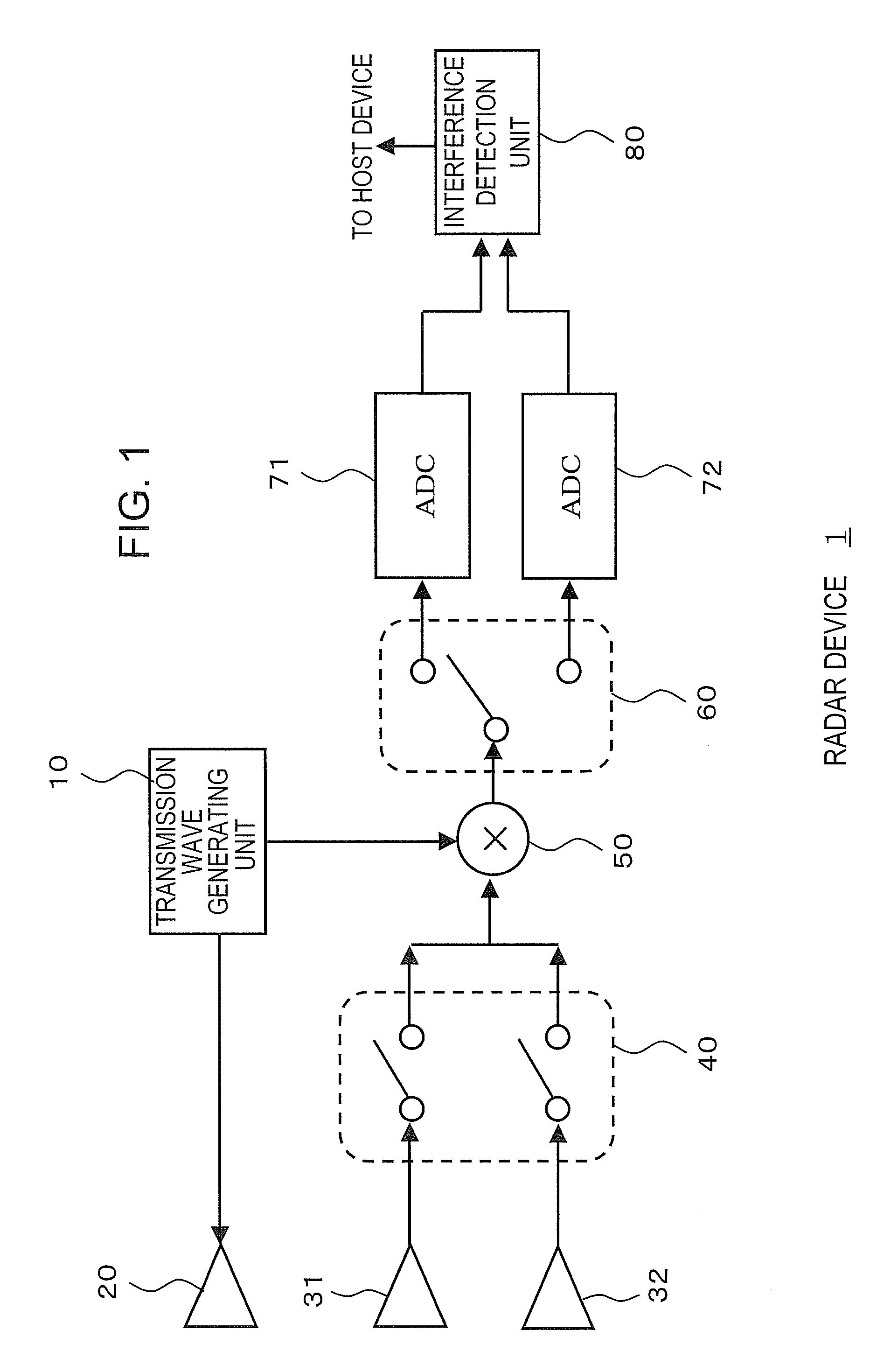
[0043] Preferred embodiments for carrying out the present invention are described hereinafter with reference to the drawings. FIG. 1 is a figure showing a configuration example of a radar apparatus 1.

[0044] The radar apparatus 1 has a transmission wave generating unit 10, a transmission antenna 20, first and second receiving antennas 31, 32, an antenna switching switch 40, a mixer 50, an output switching switch 60, first and second analog-digital converters (ADC) 71, 72, and an interference detection unit 80.

[0045] The transmission wave generating unit 10 generates a signal for forming a transmission wave which is transmitted from the transmission antenna 20. For example, a signal for forming a triangular wave is generated. The transmission wave generating unit 10 is constituted by an oscillator such as a VCO (Voltage Control Oscillator).

[0046] The transmission antenna 20 transmits a transmission wave on the basis of the signal generated from the transmission wave generating unit...

embodiment 2

[0108] Embodiment 2 is described next. Embodiment 1 above has described the radar apparatus 1 in which the two receiving antennas 31, 32 detect interference. For example, the received signal that is received by the first receiving antenna 31 is switched by the output switching switch 60 to be outputted to the first ADC 71. Also, the received signal that is received by the second receiving antenna 32 is switched by the output switching switch 60 to be outputted to the second ADC 72. The interference detection unit 80 or host apparatus can also detect a phase difference between the received signal outputted from the first ADC 71 and the received signal outputted from the second ADC 72. Therefore, in Embodiment 1 the bearing of the target can be also detected by detecting this phase difference.

[0109]FIG. 13 and FIG. 14 are figures, each showing a configuration example of the radar apparatus 1 in this Embodiment 2. As shown in FIG. 13, in the radar apparatus 1 according to Embodiment 2...


PUM


Abstract

A radar apparatus having a interference detection unit which computes an average value of received power from received signals corresponding to receiving waves received by the receiving antennas, and determines that interference has occurred when the difference between this average value and the average value of the previously computed received power is a threshold value or more. Moreover, in other interference detection method, the interference detection unit determines that interference has occurred when an average value of received power corresponding to a large distance is a threshold value or more. Furthermore, in other method, the interference detection unit determines that interference has occurred when a received power value is detected as a threshold value or more when a transmission wave is not transmitted from the transmission antenna.

Description

CROSS-REFERENCE TO RELATED APPLICATIONS [0001] This application is based upon and claims the benefit of priority from the prior Japanese Patent Application No. 2006-16593, filed on Jan. 25, 2006, the entire contents of which are incorporated herein by reference. BACKGROUND OF THE INVENTION [0002] 1. Field of the Invention [0003] The present invention relates to a radar apparatus and interference detection method for measuring the bearing and the like of a target from a reflected wave reflected on the target. [0004] 2. Description of the Related Art [0005] There has conventionally been a radar apparatus, which outputs a transmission wave from a transmission antenna and receives a reflected wave reflected on a target to measure the bearing, distance, velocity and the like of the target. For example, the radar apparatus is mounted in a vehicle and used for preventing a collision with a vehicle in front. [0006] In such the radar apparatus, interference may occur with, for example, an on...

Claims


Application Information

Patent Timeline
IPC IPC(8): G01S13/00G01S13/931
CPCG01S7/023G01S7/354G01S7/4021G01S2013/9375G01S13/931G01S2007/356G01S13/34G01S2013/93271G01S7/356
Inventor NAKANO, MASAOMIYAGAWA, KOUICHIHONDA, KANAKOSEKIGUCHI, YASUHIRO
Owner FUJITSU GENERAL LTD
Why Eureka
Try Eureka