
Touch detection for a digitizer

a digitizer and touch detection technology, applied in instruments, cathode-ray tube indicators, computing, etc., can solve the problems of inability to specifically detect an electromagnetic type stylus, low detection resolution of stylus, and additional complexity of both sensors and electronics

Active Publication Date: 2007-07-26
MICROSOFT TECH LICENSING LLC
View PDF99 Cites 130 Cited by
  • Summary
  • Abstract
  • Description
  • Claims
  • Application Information

AI Technical Summary

Benefits of technology

[0041] Preferably, there is provided at least a second conductor located within the sensor and having a junction with the at least one conductor, wherein the source of oscillating electrical energy is applied to one of the conductors and the junction is configured such that a touch by a conductive object causes an a.c short at the junction, the detector being configured to detect the oscillating signal at the second conductor as the capacitive effect and to infer the touch.

Problems solved by technology

The major disadvantage of this method is the additional complexity to both sensor and electronics.
Two major disadvantages of the above patents are low resolution of the stylus detection and inability to specifically detect an electromagnetic type stylus.
Therefore the resolution of the stylus detection is limited to the proximity of the lines\pixels.
The main disadvantages of this method are that it requires an arithmetic unit for calculating the weighted average of the sampled values, it does not allow the detection of an EM stylus and the sensor is not transparent.
The disclosure does not allow the detection of an EM stylus together with finger detection.
The sensor's plates\pixels are not transparent and therefore cannot be mounted on a display screen.
Disadvantages of the detection system disclosed therein are that it does not allow the detection of an EM stylus.
Rather it requires current flows from both ends of the conductive surface which is in evidently power consuming.
Furthermore, the detection is analog and involves relatively complicated circuitry.
Disadvantages of the above invention are the inability to detect an EM stylus, low update rate and limited resolution.
The most evident disadvantages of this invention is the need for additional hardware and the inability to detect an EM stylus.

Method used


Image

  • Touch detection for a digitizer
  • Touch detection for a digitizer
  • Touch detection for a digitizer

Examples


first embodiment

a. First Embodiment

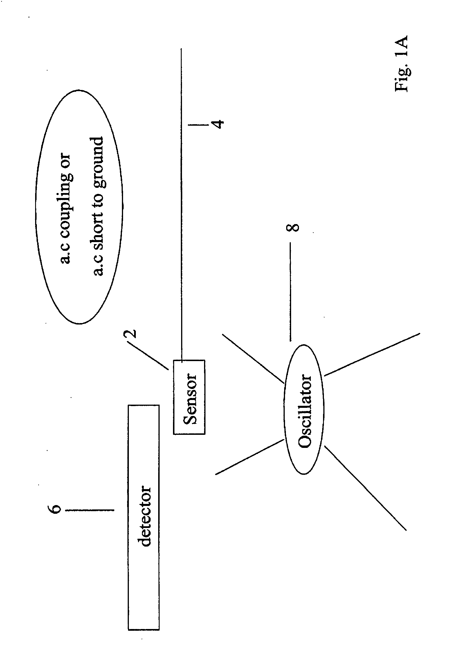
[0142] This method utilizes an electromagnetic wave transmitted from either an external source or by the sensor components and received by the user body. When the user's finger touches the sensor the EM energy transfers from the user to the sensor. The detector processes the signal and determines the finger's position.

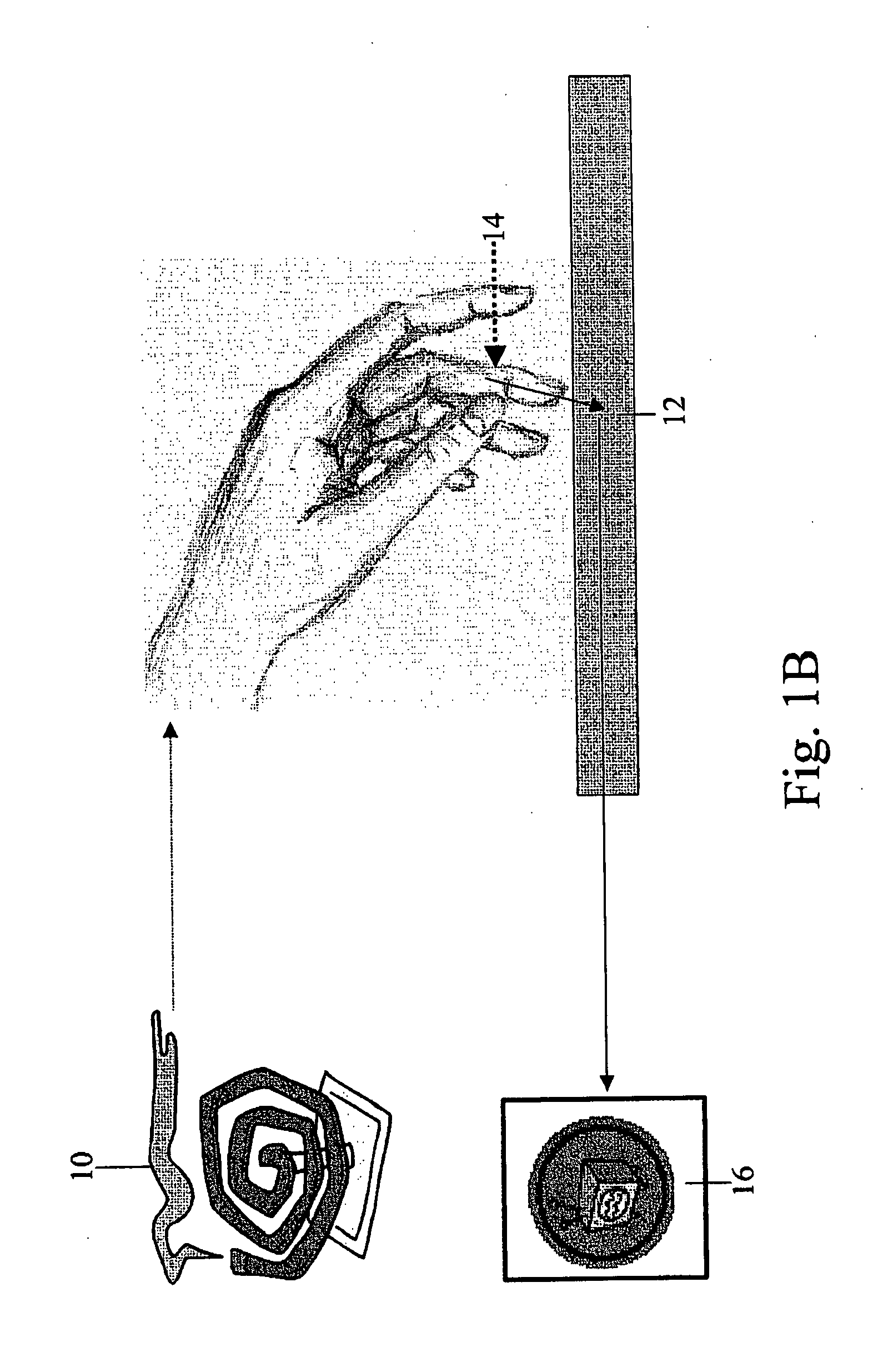
[0143] Reference is now made to FIG. 1B, which is a general description of a first finger detection apparatus according to the present invention. An external source 10 transmits electromagnetic wave energy, which is absorbed by the user's body. If the user now touches the sensor 12 a capacitance is formed between the finger 14 and the sensor conductors. The received signal is at a frequency that allows it to pass through the capacitance at the level typically formed, and thus the received signal passes from the user's finger 14 to the sensor 12. Detector 16, which processes the sensed signals, determines the position of the user's finger.

[0144] In ...

second embodiment

b. Second Embodiment

[0158] The second embodiment does not require transmitting an EM signal to the user's body. Rather, even without the influence of an EM signal, the user's finger adds a capacitance that connects two orthogonal sensor lines.

[0159] Reference is now made to FIG. 2, which is a general description of the second finger detection embodiment of the present invention. A two-dimensional sensor matrix 20 lies in a transparent layer over an electronic display device. An electric signal 22 is applied to a first conductor line 24 in the two-dimensional sensor matrix 20. At each junction between two conductors a certain minimal amount of capacitance exists. A finger 26 touches the sensor 20 at a certain position and increases the capacitance between the first conductor line 24 and the orthogonal conductor line 28 which happens to be at or closest to the touch position. As the signal is AC, the signal crosses by virtue of the capacitance of the finger 26 from the first conducto...

third embodiment

c. Third Embodiment

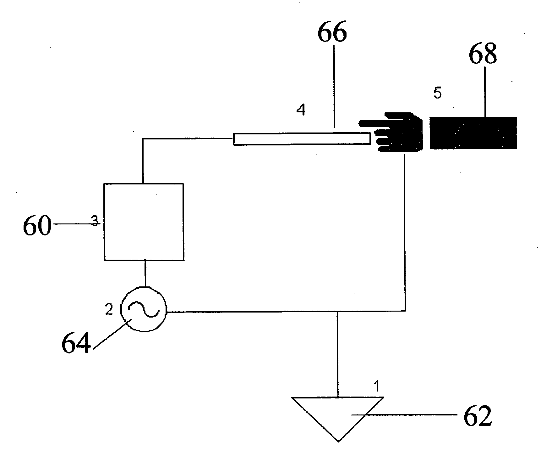
[0169] The third embodiment uses a potential difference between the user's finger and the system to determine the finger position.

[0170] Reference is now made to FIG. 4, which is a simplified schematic diagram illustrating the third preferred embodiment of the finger detection of the present invention. A detector 60 is connected to ground 62. The detector is connected to an oscillator 64 that provides an alternating signal which can cause the detector potential to oscillate with respect to ground potential. The oscillating potential is applied to sensor 66.

[0171] In operation the detector 62 oscillates in reference to the common ground potential. As a user's finger 68 touches the sensor 66, a capacitance is formed between the finger and the sensor conductors. Now the user's body potential does not oscillate in reference to earth while the sensor's potential does oscillate in reference to the common ground potential. Thus an alternating difference in potential be...


PUM


Abstract

A detector for detecting touches of at least one object on a transparent sensor located over a display screen, the detector comprising. a display screen; a patterned arrangement of conductors extending into said sensor situated over said display screen; and detection circuitry adapted to detect capacitive coupling of said at least one object with said at least one conductor.

Description

RELATED APPLICATIONS [0001] This application is a Divisional of U.S. patent application Ser. No. 10 / 757,489 filed on Jan. 15, 2004, which claims the benefit of U.S. Provisional Patent Application No. 60 / 446,808 filed on Feb. 10, 2003, and U.S. Provisional Patent Application No. 60 / 501,484 filed on Sep. 5, 2003, the contents of which are hereby incorporated by reference.FIELD AND BACKGROUND OF THE INVENTION [0002] The present invention relates to a combined touch and stylus digitizer and, more particularly, but not exclusively to adaptations for the detection of finger touch. [0003] The popularity of computers has given rise to extensive research and development in the field of digitizers and touch screens. There are many inventions describing touch panels but very few describe a digitizer capable of detecting both an EM stylus and finger touch using the same sensing device. U.S. patent application Ser. No. 09 / 629,334 “Physical Object Location Apparatus and Method and a Platform usin...

Claims


Application Information

Patent Timeline
Patent Type & Authority Applications(United States)
IPC IPC(8): G06F3/041
CPCG06F3/041G06F3/044G06F3/046G06F3/0416G06F3/02G06F2203/04106G06F3/0488G06F3/0442G06F3/0446G06F3/04162G06F3/04166G06F3/04182
Inventor PERSKI, HAIMMORAG, MEIR
Owner MICROSOFT TECH LICENSING LLC
Features
  • Generate Ideas
  • Intellectual Property
  • Life Sciences
  • Materials
  • Tech Scout
  • Unparalleled Data Quality
  • Higher Quality Content
  • 60% Fewer Hallucinations
Learn More