Switchplate Area Light

Inactive Publication Date: 2007-07-26
NITE IZE INC
View PDF23 Cites 34 Cited by
  • Summary
  • Abstract
  • Description
  • Claims
  • Application Information

AI Technical Summary

Benefits of technology

[0033] (k) The design eliminates many of the parts described in prior art. It requires no protruding frame, no separate electronics box unattached to the switchplate, no structure to hold an array of

Problems solved by technology

(c) The LED is deliberately driven below its rated input, resulting in extremely long life.
If t

Method used


Image

  • Switchplate Area Light
  • Switchplate Area Light
  • Switchplate Area Light

Examples


Embodiment Construction

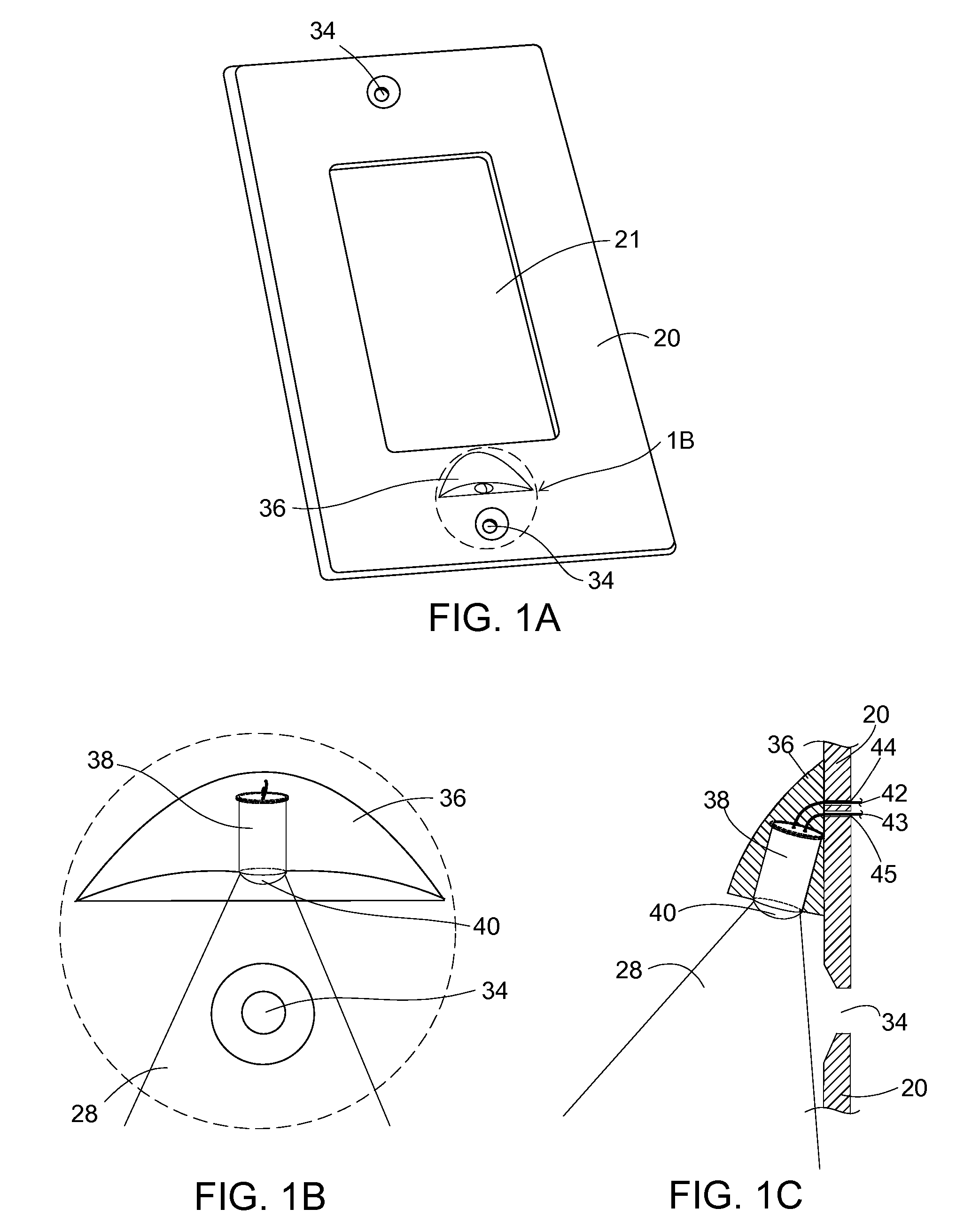
—FIGS. 1A, 1B, 1C, AND 3A-PREFERRED EMBODIMENT

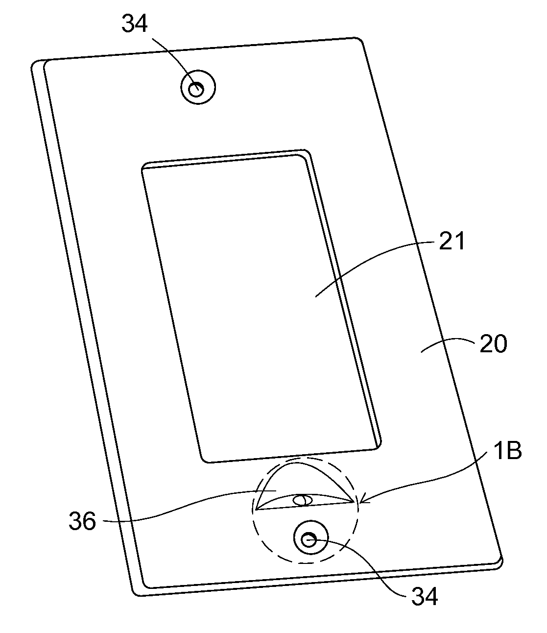
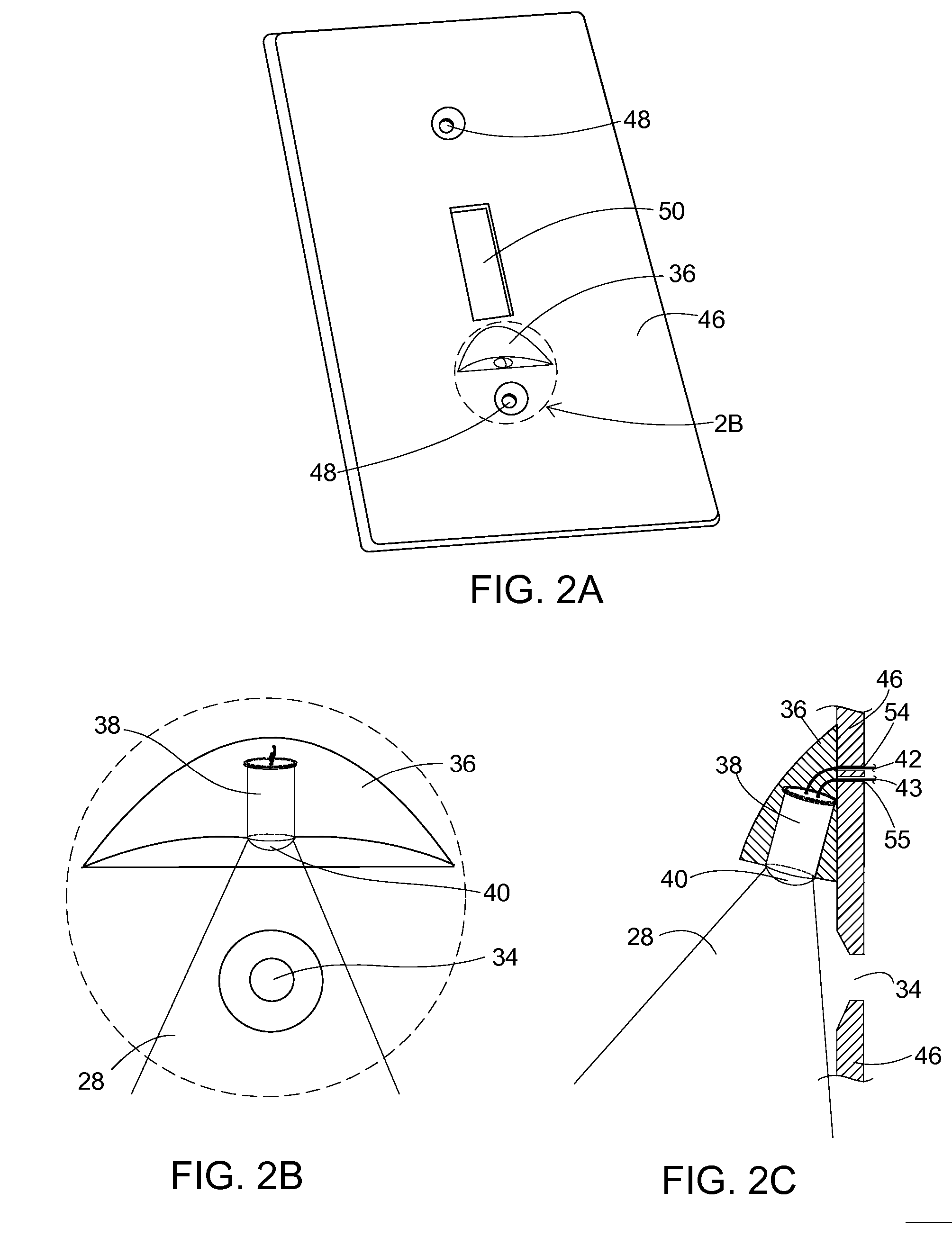
[0108] The preferred embodiment of the present invention is illustrated from the front in FIG. 1A and back in FIG. 3A. A cylindrical LED 38 is molded or fitted into a housing 36 on the structure of the switchplate 20 at such an angle that the light rays 28 emanating from the LED 38 provide illumination on the pathway below the switchplate. Other than the leads 42 and 43 exiting the LED 38 which protrude though holes 44 and 45 in the switchplate 20, the LED 38 is mounted entirely on the front of the switchplate 20. The housing 36 surrounding the LED 38 is of such a composition that it allows some light to escape. Alternatively, the switchplate 20 itself may be modified to provide an enclosure for the LED 38 that angles it away from the plane of the switchplate in the same manner as with a separate housing 36. The built-in lens 40 molded into the end of the LED 38 protrudes from the housing 36 and is not covered by the housing.

[0109] The ...


PUM


Abstract

A light emitting diode (LED) and associated driver circuit wherein the LED is mounted on the front of a switchplate and the driver circuit on the back of the switchplate. The LED is mounted at a downward angle on the outside of the switchplate so as to light a pathway beneath the switchplate. The drive electronics are designed to work with a return path through an electrical load. Additionally, the LED driver circuit is designed to allow operation of the LED with both resistive and reactive loads controlled by the switch to which the switchplate is connected. The device is also designed to be connected to any electrically valid combination of 2-way, 3-way, and 4-way switches either singly or in combination.

Description

CROSS-REFERENCE TO RELATED APPLICATIONS [0001] This application claims the benefit of provisional patent application Ser. No. 60 / 760,626 filed 2006 Jan. 21 by the present inventor.FEDERALLY SPONSORED RESEARCH [0002] Not Applicable SEQUENCE LISTING OR PROGRAM [0003] Not Applicable BACKGROUND OF THE INVENTION [0004] 1. Field of Invention [0005] This invention relates to alternating current powered night lights, specifically to such night lights where the load controlled by a switch or switches is used as the electrical return path. [0006] 2. Prior Art [0007] There are many night lights on the market in this crowded field of art. However, few provide a return path for current used to power a light through a load controlled by a switch. Most current night lights plug into an existing outlet receptacle and light a small area with a low level of light. U.S. Pat. No. 6,561,677 (2003) by Leen is one example. Others are wired into an outlet box. U.S. Pat. No. 6,547,411 B1 (2003) by Dornbusch...

Claims


Application Information

Patent Timeline
IPC IPC(8): F21V33/00
CPCF21S8/035H01H9/18Y02B20/343H05B33/0809H05B33/0812H05B33/0803H05B45/395Y02B20/30Y10S362/80
Inventor GLAZNER, GREGORYF
Owner NITE IZE INC
Why Eureka
Try Eureka