Sealed battery

Inactive Publication Date: 2007-07-26
SANYO ELECTRIC CO LTD
View PDF2 Cites 42 Cited by
  • Summary
  • Abstract
  • Description
  • Claims
  • Application Information

AI Technical Summary

Benefits of technology

[0031]Preferably in this aspect, the thickness of the interposed material exceeding 70% of that of the terminal cap makes it difficult for the interposed m

Problems solved by technology

However, the PTC thermistor element serving as a safety device in nonaqueous electrolyte secondary batteries as disclosed in JP-2001-15155-A restricts the amount of current to be supplied.
However, the temperature of the batteries may reach 80 degrees Celsius or more, whereby repeated use may cause heat effects on the PP insulating gasket 27 provided between the terminal cap 19 and bottom plate 20.
However, the sealing body used here has a problem in that a current keeps flowing even if something abnormal happens in the battery, for example, the shape of the safety valve changes or the battery opens with an increased internal gas pressure, since the positive electrode terminal cap, safety valve, and bottom plate are spot-welded and there is no current interrupt means provided between the terminal cap and bottom plate.
Since aluminum has extremely high heat conductivity compared with iron-ba

Method used


Image

  • Sealed battery
  • Sealed battery
  • Sealed battery

Examples


Example

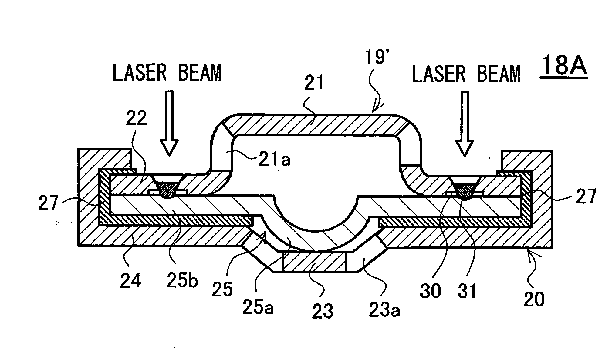
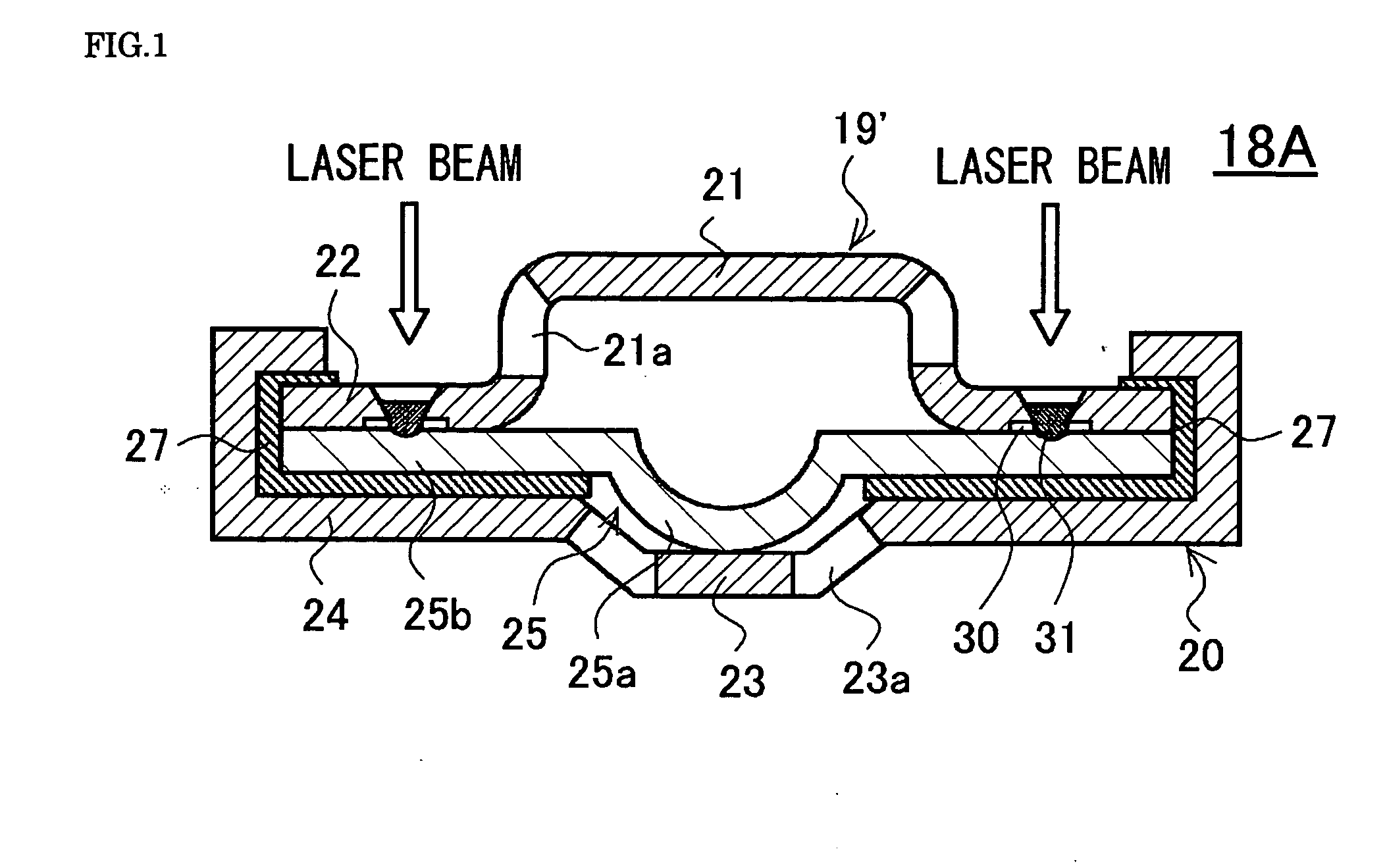
[0040]A manufacturing process of a sealing body 18A according to the first embodiment will now be described. The dish-shaped bottom plate 20 made of aluminum and having the same structure as that used in the above-described related-art sealing bodies is prepared. The bottom plate 20 has the concave portion 23 protruding inwardly of the battery, and the flat flange 24 serving as the base of the concave portion 23. At the corner edge of the concave portion 23, the gas vent hole 23a is formed. On the flange 24 of the bottom plate 20, the annular insulating gasket 27 made of PP is mounted. Also as in the above-described related art, the safety valve 25 made of aluminum foil that is 0.2 mm thick, for example, and including the concave portion 25a and the flange 25b is placed so that the flange 25b is laid upon the insulating gasket 27 and the concave portion 25a of the safety valve 25 is laid upon the concave portion 23 of the bottom plate 20. The bottommost part of the concave portion 2...

Example

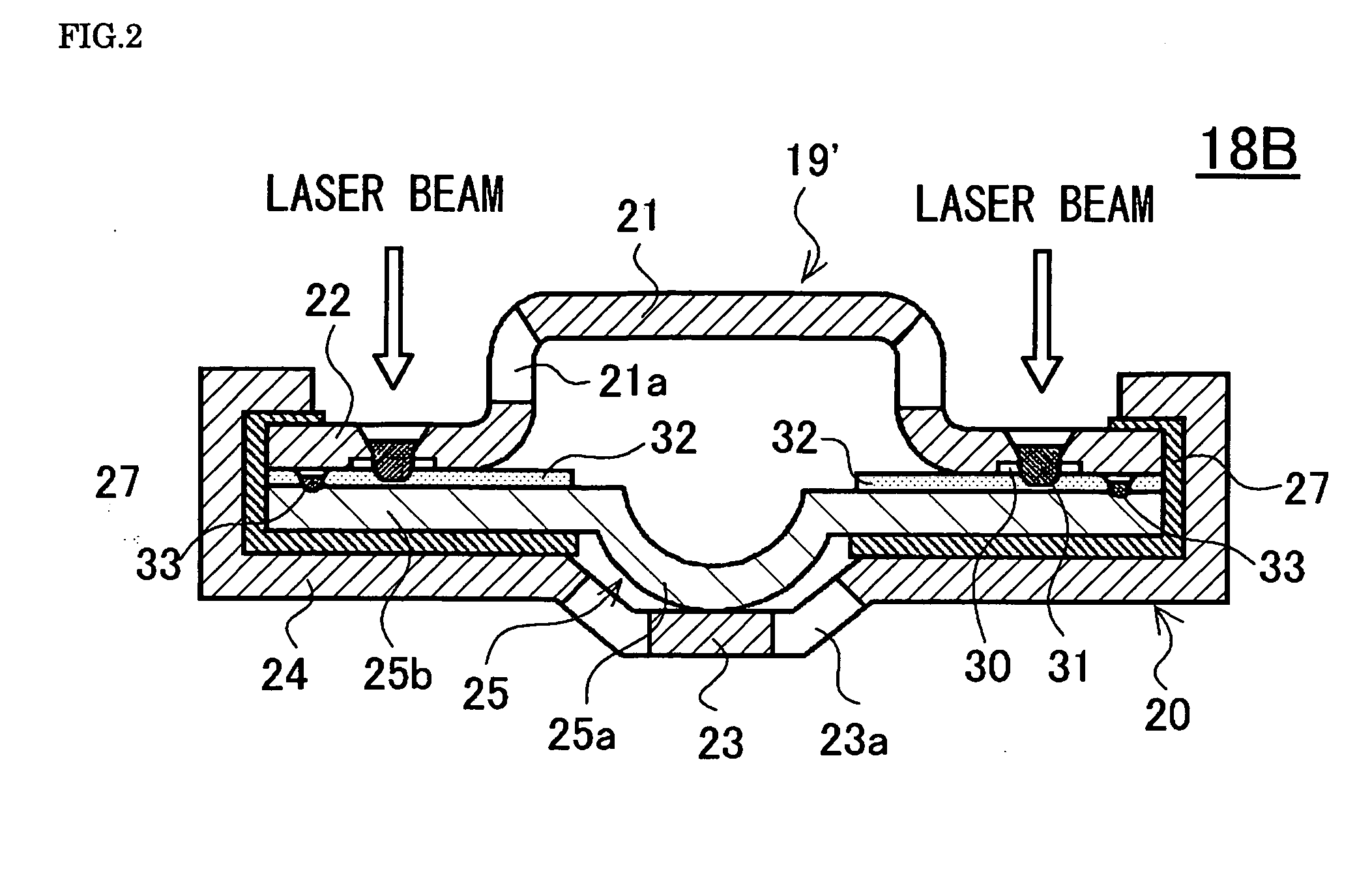
[0043]A sealing body 18B according to a second embodiment of the invention is manufactured through a process similar to that of the first embodiment, except that an interposed material 32 is added between the safety valve 25 and terminal cap 19′. Here, the interposed material 32 is annular, half as thick as the safety valve 25, and made of the same aluminum-based material as the safety valve 25. The material is placed on the flange 25b of the safety valve 25. Subsequently, four points are laser-welded at regular intervals from the surface of the interposed material 32 for uniting the interposed material 32 and safety valve 25. With the terminal cap 19′ having the annular groove 30 as in the first embodiment placed on the surface of the interposed material 32, four points corresponding to the groove 30 are laser-welded at regular intervals from the terminal cap 19′ side as in the first embodiment for fixing the flange 24 of the bottom plate 20. The sealing body 18B having a current i...


PUM


Abstract

A sealed battery according to the present invention includes a sealing body 18A having a terminal cap 19′ made of an iron-based material and a safety valve 25 made of an aluminum-based material. In the sealing body 18A, at least one of the flange of the terminal cap 19′ and the flange of the safety valve 25 has a portion defining a space 30. The flanges of the terminal cap and of the safety valve are welded at a position corresponding to the space with high-energy rays. It is thus possible to provide the sealed battery including the sealing body having a current interrupt function in which resistance between the terminal cap and the safety valve is kept low, thereby being suitable for large-current applications.

Description

FIELD OF THE INVENTION[0001]The present invention relates to a sealed battery. More particularly, the present invention relates to a sealed battery including a sealing body having a current interrupt function in which a negative electrode or positive electrode terminal cap and a safety valve are directly welded with a laser beam or other high-energy rays for increasing the welding strength between the two without increasing the electrical resistance of the battery in use.BACKGROUND OF THE INVENTION[0002]The ongoing surge in the development of lightweight and space economical electronic devices has raised the need for lighter and smaller batteries as their power supplies. To meet this requirement, sealed nonaqueous electrolyte secondary batteries represented by lithium-ion secondary batteries, which are compact, lightweight, high capacity, chargeable and dischargeable, have been in practical use for compact camcorders, mobile phones, notebook computers, and other mobile electronics a...

Claims


Application Information

Patent Timeline
IPC IPC(8): H01M2/08H01M2/12H01M50/169
CPCH01M2/1241H01M2/0413Y02E60/10H01M50/171H01M50/3425H01M50/169H01M50/10H01M50/183
Inventor YAMASHITA, SHUICHIOHGI, MASANORISUWA, HIROMITSUOKAZAKI, YASUNORI
Owner SANYO ELECTRIC CO LTD
Why Eureka
Try Eureka