
Plunger

a technology of iols and iols, applied in the field of iols, can solve the problems of affecting the use effect of iols, affecting the haptic and optics, and the performance of iol tip designs is less than optimal, and achieves the effect of increasing the chance of infection

Inactive Publication Date: 2007-07-26
ALCON INC
View PDF20 Cites 23 Cited by
  • Summary
  • Abstract
  • Description
  • Claims
  • Application Information

AI Technical Summary

Benefits of technology

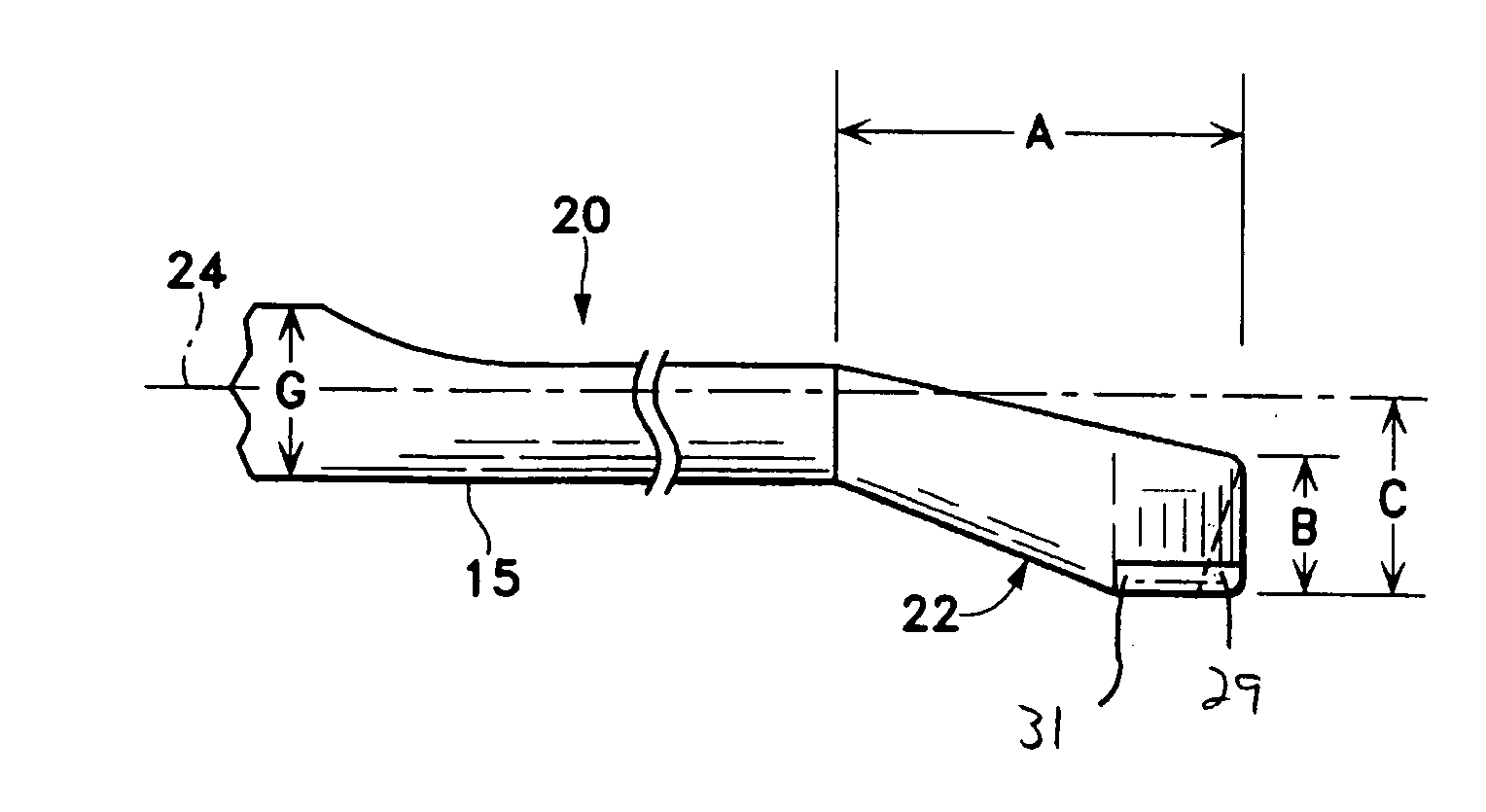
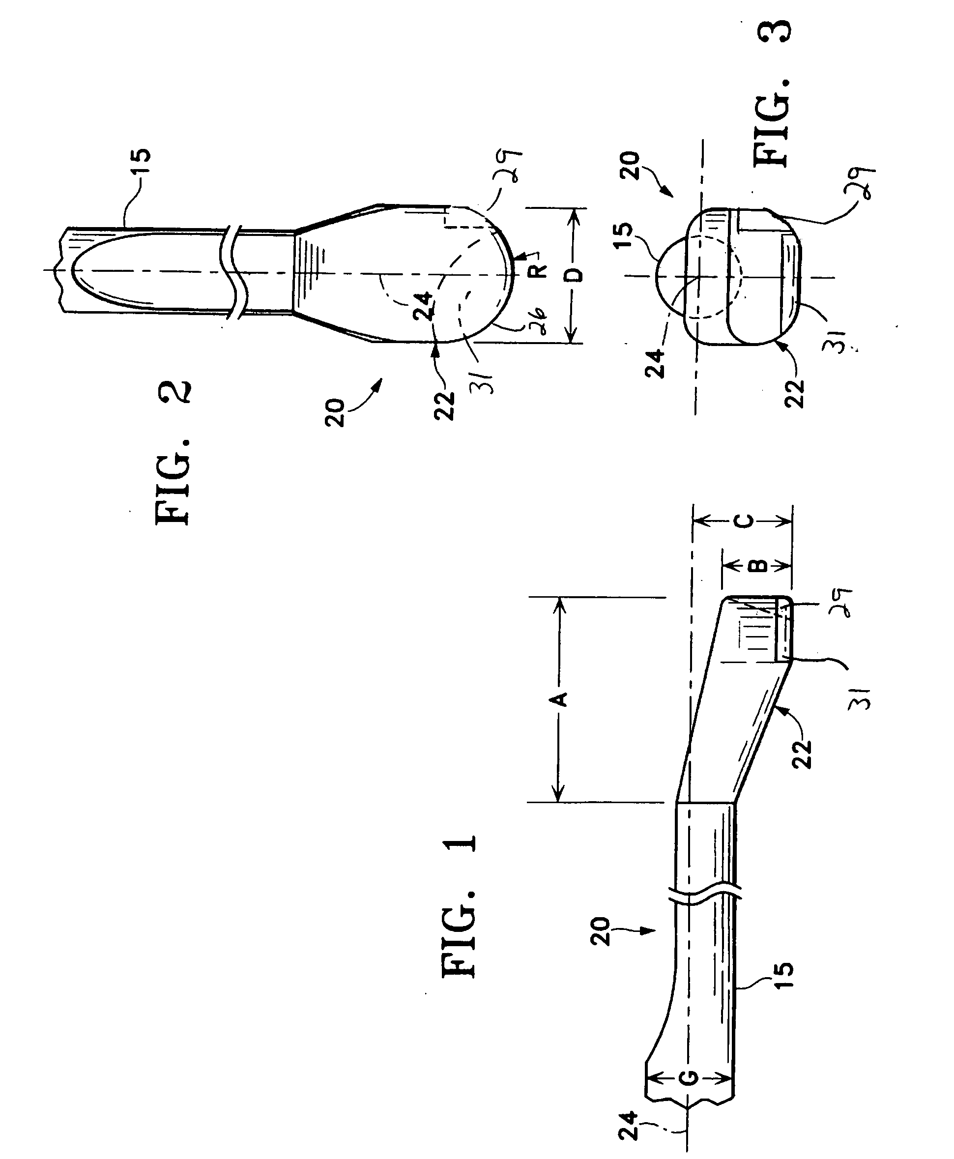
[0006] The present invention improves upon prior art lens injector plungers by providing a plunger having a blunt, rounded tip offset from the centerline of the plunger rod and having a notch. The offset tip assures that the tip is biased downward against the bottom of the cartridge bore. Such a downward bias helps prevent the tip from riding up over the IOL and being folded within the IOL. The notch provides a space for the haptic to rest while the IOL is being pushed down the bore of the cartridge so that the haptic does not get trapped between the bore sidewall and the plunger tip. An additional improvement upon the prior art is that the IOL optic and haptics are all managed at the most forward tip of the plunger / cartridge, allowing the IOL to be inserted into its final position in the capsular bag in one step rather than multiple steps that increases the chances of infection.
[0009] It is a further object of the present invention to provide a lens injector plunger that minimizes the potential for damage to the optic and / or the haptics.

Problems solved by technology

When trauma, age or disease cause the lens to become less transparent, vision deteriorates because of the diminished light which can be transmitted to the retina.
While these symmetric plunger tip designs work well with robust, rubbery, elastic lens materials, the performance of these tip designs is less than optimal when used with an IOL produced with the characteristics of a viscoelastic material, such as a soft acrylic.
In particular, the tip design that encourages the haptic on multipiece and single piece IOLs to get caught between the tip and the inner lumen of the bore in the cartridge, thereby damaging the haptic and the optic, in some instances.

Method used


Image

  • Plunger
  • Plunger
  • Plunger

Examples


Embodiment Construction

[0012] As best seen in FIG. 4, intraocular lens injectors suitable for use with the present invention generally consist of handpiece 12, cartridge 10 and plunger 14. Cartridge 10 contains bore 16 having a bore wall 28 through which the intraocular lens (not shown) is pushed by plunger 14 until the lens exist bore 16 at nozzle 18. Cartridge 10 and handpiece 12 may be of any suitable design well-known in the art.

[0013] As best seen in FIGS. 1-3 plunger 14 contains tip 20 that contains IOL contacting portion 22 that is off set asymmetrically relative to longitudinal centerline 24. Portion 22 also contains convexly rounded nose 26. Length A of portion 22 preferably is between 0.10 inches and 0.20 inches, with 0.127 inches being preferred. Width D of portion 22 preferably is between 0.060 inches and 0.100 inches, with 0.083 inches being most preferred. The radius R of nose 26 may be any suitable dimension, with between 0.030 inches and 0.050 inches being preferred and 0.042 inches being...


PUM


Abstract

A plunger having blunt, rounded tip offset from the centerline of the plunger rod and having a notch. The offset tip assures that the tip is biased downward against the bottom of the cartridge bore. Such a downward bias helps prevent the tip from riding up over the IOL and being folded within the IOL. The notch provides a space for the haptic to rest while the IOL is being pushed down the bore of the cartridge so that the haptic does not get trapped between the bore sidewall and the plunger tip.

Description

BACKGROUND OF THE INVENTION [0001] This invention relates to intraocular lenses (IOLs) and more particularly to plungers used to inject an IOL into an eye. [0002] The human eye in its simplest terms functions to provide vision by transmitting and refracting light through a clear outer portion called the cornea, and further focusing the image by way of the lens onto the retina at the back of the eye. The quality of the focused image depends on many factors including the size, shape and length of the eye, and the shape and transparency of the cornea and lens. When trauma, age or disease cause the lens to become less transparent, vision deteriorates because of the diminished light which can be transmitted to the retina. This deficiency in the lens of the eye is medically known as a cataract. The treatment for this condition is surgical removal of the lens and implantation of an artificial lens or IOL. More recently, IOLs are being used in purely refractive procedures where patients may...

Claims


Application Information

Patent Timeline
IPC IPC(8): A61F9/00
CPCA61F2/1664
Inventor IWASAKI, TAKUYA
Owner ALCON INC
Learn More