Stop determination apparatus, inclination determination apparatus, and electric parking brake controller

Active Publication Date: 2007-07-26
SUBARU CORP
View PDF10 Cites 44 Cited by
  • Summary
  • Abstract
  • Description
  • Claims
  • Application Information

AI Technical Summary

Benefits of technology

[0026](6) The determination of a stop can be made according to a convergence of variations in the output of the G sensor caused by the behavior of the vehicle in the direction of pitching of the vehicle. Since such pitching occurs while the vehicle is stopped and then diminishes in a short period of time, it is possible to ensure that the determination of a stop is made very soon after the actual stop.
[0027](7) The determination of a stop can be established when variations in the output of the G sensor are equal to or less than a threshold value over a predetermined period of time, thereby allowing the use of a simple logic to make a proper determination of a stop.
[0028](8) Using the result of the aforementioned determination of a stop, the electric actuator is activated to drive the parking brake. This arrangement will prevent erroneous activation before the vehicle is stopped or any increase in time lag between the stop of the vehicle and a brake application, thereby allowi

Problems solved by technology

However, such a vehicle speed sensor cannot accurately detect the speed of the vehicle running at an extremely low speed immediately before the vehicle is being stopping.
For example, it may be impossible to detect when the vehicle is running at an actual speed of about 2 km/h or less.
However, with this conventional technique, the determination of a stop of the vehicle is made only on the basis of this elapsed period of time after the vehicle speed cannot be detected.
Furthermore, using this conventional technique, it is difficult to accurately estimate the timing of a stop.
Howe

Method used


Image

  • Stop determination apparatus, inclination determination apparatus, and electric parking brake controller
  • Stop determination apparatus, inclination determination apparatus, and electric parking brake controller
  • Stop determination apparatus, inclination determination apparatus, and electric parking brake controller

Examples


first embodiment

[0050]A description will now be made of an electric parking brake system in accordance with a first embodiment of the present invention.

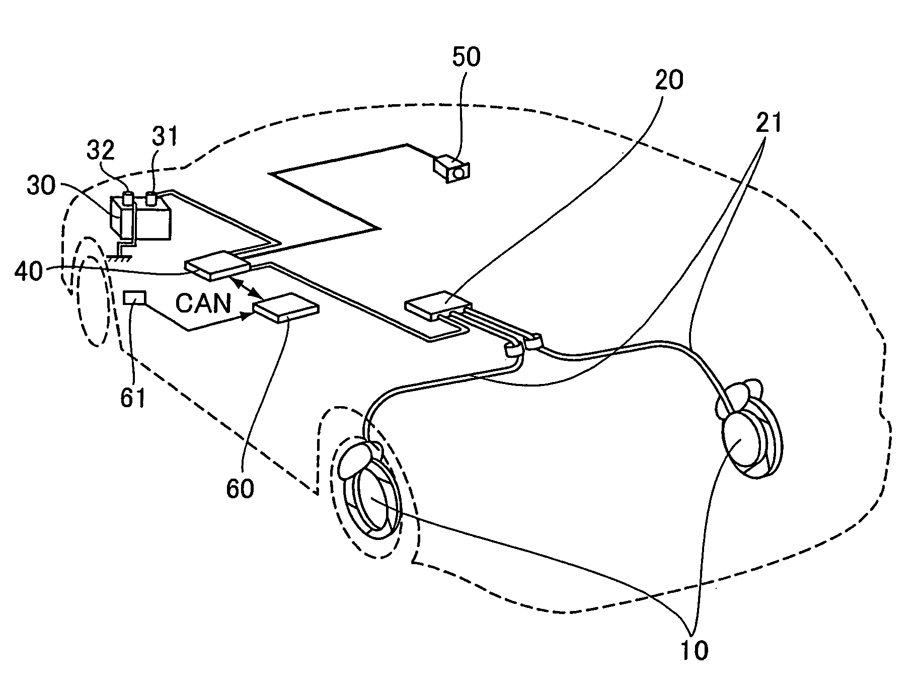
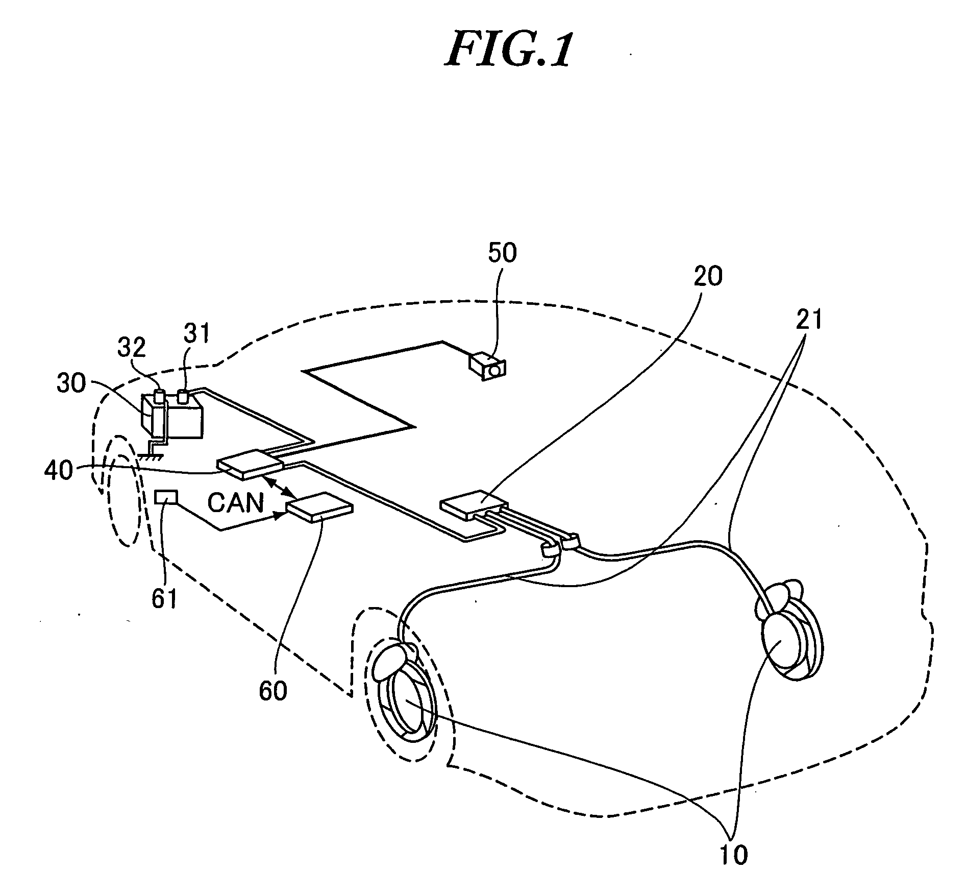
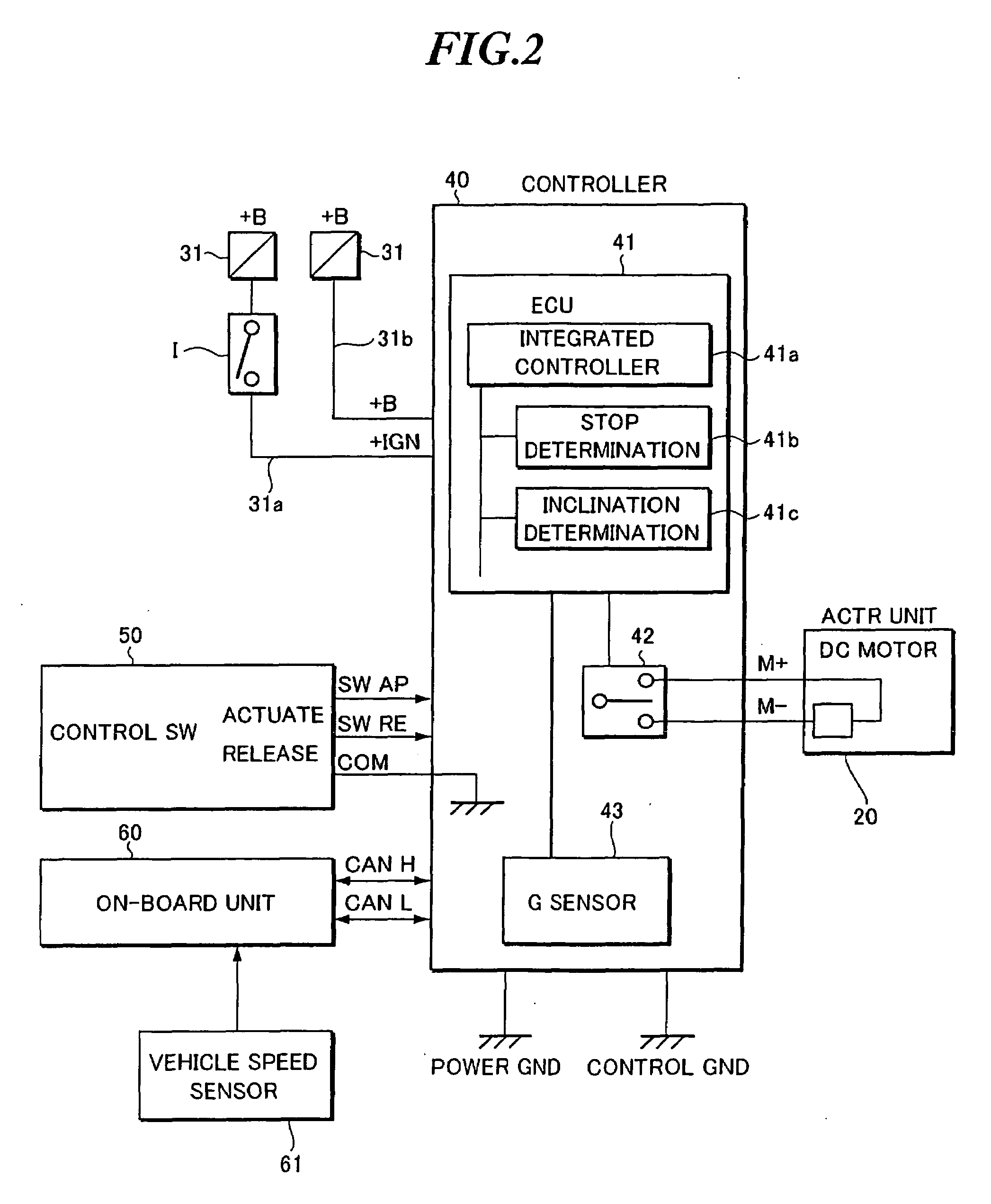
[0051]FIG. 1 is a view illustrating the mechanical configuration of an electric parking brake system of this embodiment. FIG. 2 is a block diagram illustrating the circuit configuration of the electric parking brake system.

[0052]The electric parking brake system includes a parking brake 10, an actuator unit 20, a battery 30, a controller 40, a control switch 50, and an on-board unit 60.

[0053]The parking brake 10 is a braking mechanism for applying brakes to the drive wheels of the vehicle in order to prevent unintentional movement of the vehicle, for example, when the vehicle is parked or at a stop. The brake 10 is installed at each wheel hub portion of the right and left rear wheels of the vehicle. The parking brake 10 is of a type known as a drum-in-disk brake which includes a brake drum (not shown) disposed on the inner diameter side of the rotor...

modified examples

[0182]It is to be understood that various modifications and variations can be made to the present invention without being limited to the aforementioned embodiment, and those modifications and variations fall within the scope of the present invention.

[0183](1) This embodiment relates, for example, to a stop determination for the electric parking brake system; however, the vehicle stop determination method and apparatus of the present invention are not limited thereto. The invention may also be applicable to any other applications which require a determination of a stop of a vehicle, and is preferably applicable particularly to those in which the determination of a stop is employed as a trigger to perform switching between activation and deactivation. For example, the method and apparatus are also applicable to a stop determination in stop-and-go traffic or to a stop determination for determining the possibility of an idle stop.

[0184](2) The embodiment is adapted to detect a change in...

second embodiment

[0189]A description will now be made of an electric parking brake system in accordance with a second embodiment of the present invention.

[0190]FIG. 9 is a flowchart showing the logic of the stop and inclination determinations for the electric parking brake system of the second embodiment. FIG. 10 shows graphs of the histories of the vehicle speed sensor output and the G sensor output of a vehicle being stopping, in which the vehicle includes the electric parking brake system of the second embodiment.

[0191]The steps of the operation of FIG. 9 will be described below in the order in which they appear.

[0192]To begin with, those variables that are used in the description below will be explained.

[0193]“g_stock” or a g sensor value or an output from the G sensor 43, which is temporarily retained by the ECU 41, is equal to 0 in the initial state (at the start of logic) and will be updated, when “timer” is reset, with a g sensor value given then, as will be discussed later.

[0194]“timer” is ...


PUM


Abstract

A vehicle stop determination apparatus includes a vehicle speed sensor for detecting a speed of a vehicle, a G sensor for detecting a longitudinal acceleration of a vehicle, an inclination acceleration estimate section for calculating an estimated inclination acceleration resulting from an inclination of a road surface based on a vehicle speed reduction rate calculated from an output of the vehicle speed sensor and an output from the G sensor, and a stop determination section which has a first stop determination mode and a second stop determination mode and which selects the first stop determination mode or the second stop determination mode based on the vehicle speed reduction rate provided before the output of the vehicle speed sensor becomes equal to or less than a detection limit. Also, the inclination is re-determined based on the output of the G sensor when the vehicle is stopped.

Description

BACKGROUND OF THE INVENTION[0001]1. Field of the Invention[0002]The present invention relates to a stop determination apparatus for determining whether a vehicle such as an automobile is at a standstill, an inclination determination apparatus for determining an inclination of the road surface on which the vehicle such as an automobile is stopped, and an electric parking brake controller which incorporates both these apparatuses.[0003]The present application claims each priority from Japanese Patent Application Nos. 2006-001667, 2006-051635, and 2006-274991, the respective disclosures of which are incorporated herein by reference.[0004]2. Description of the Related Art[0005]An electric parking brake actuates a parking brake during vehicle parking or stopping using, for example, an electric actuator such as a motor. Such an electric parking brake can be operated by a vehicle operator using electrical switches, thus allowing reduced operator efforts when compared to a manual lever or f...

Claims


Application Information

Patent Timeline
IPC IPC(8): G05D1/00
CPCB60T7/12B60T8/172B60T13/74G01P13/00B60W30/18118B60W2550/142B60T2201/06B60W2552/15
Inventor NAKAYAMA, DAISUKE
Owner SUBARU CORP
Why Eureka
Try Eureka