Optical network for bi-directional wireless communication

a wireless communication and optical network technology, applied in the field of bi-directional wireless communication, can solve problems such as degradation, and achieve the effect of preventing degradation

Inactive Publication Date: 2007-07-26
SAMSUNG ELECTRONICS CO LTD
View PDF6 Cites 53 Cited by
  • Summary
  • Abstract
  • Description
  • Claims
  • Application Information

AI Technical Summary

Benefits of technology

The present invention aims to solve the problems and disadvantages in current wireless communication networks by providing a bi-directional network that prevents signal degradation without the need for a control signal.

Problems solved by technology

The patent text describes a problem in designing optical networks for wireless communication. The problem is that existing networks have limitations in terms of the area they can occupy and the various wireless communication methods they can use. The text proposes a solution that combines the use of heterogeneous data transmission methods, such as time division multiplexing and sub-carrier multiplexing, to improve communication capacity and rate. The text also describes a conventional optical network and a modified version of it that separates the downstream and upstream optical signals to prevent mutual interference and improve network performance.

Method used


Image

  • Optical network for bi-directional wireless communication
  • Optical network for bi-directional wireless communication
  • Optical network for bi-directional wireless communication

Examples


Embodiment Construction

[0024]Embodiments of the present invention will be described herein below with reference to the accompanying drawings. In the drawings, the same or similar elements are denoted by the same reference numerals even though they are depicted in different drawings. For the purposes of clarity and simplicity, well-known functions or constructions are not described in detail since they would obscure the invention in unnecessary detail.

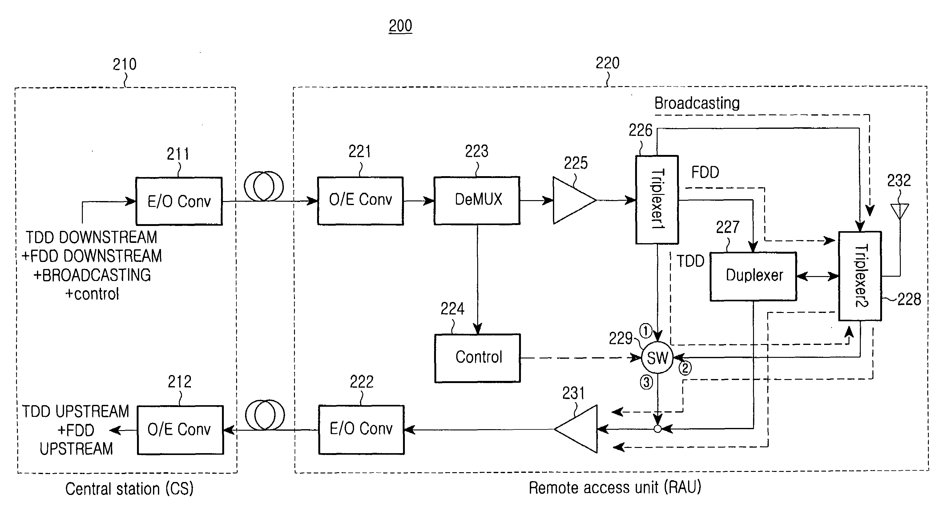
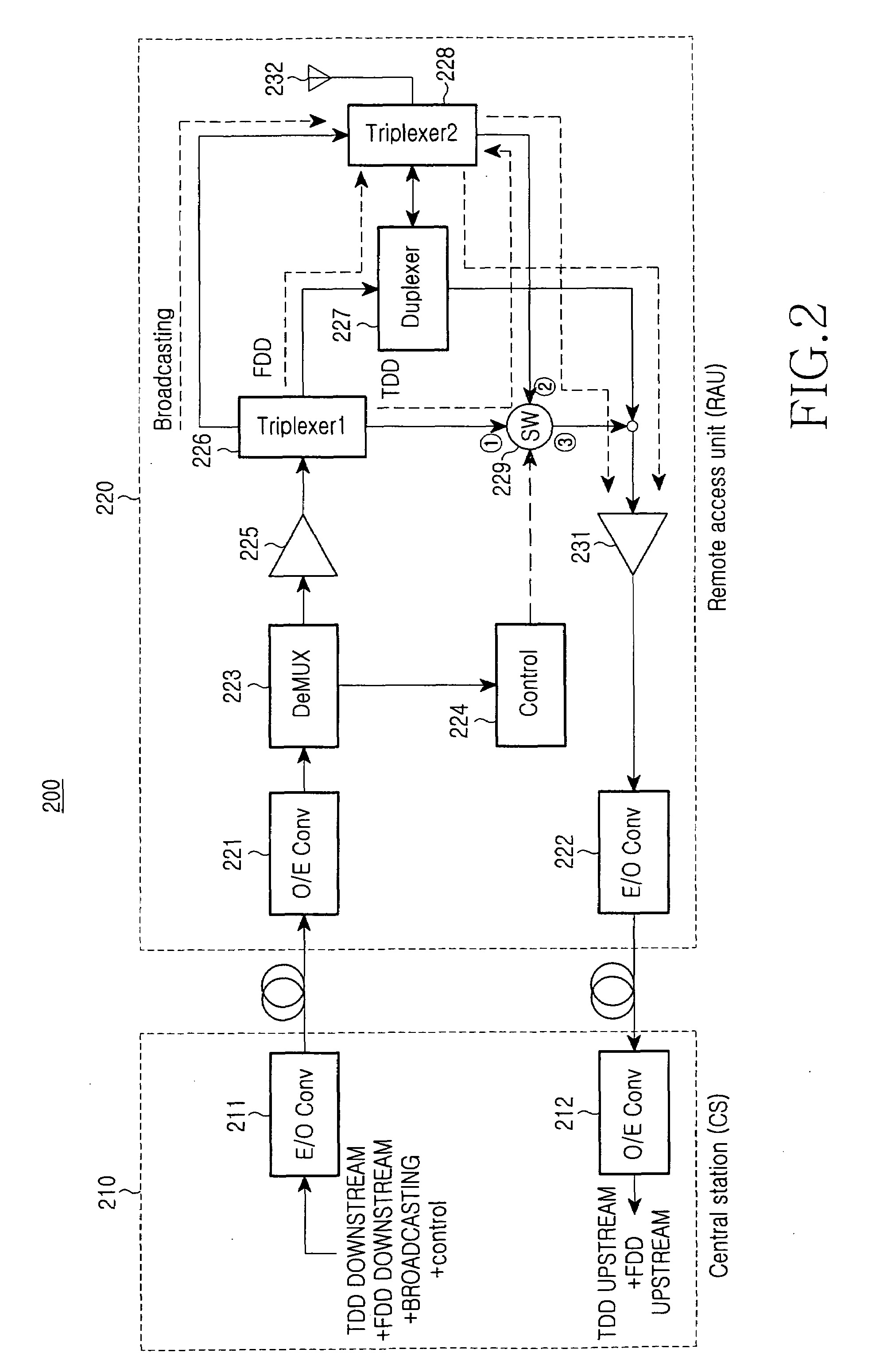
[0025]FIG. 3 is a schematic diagram of an optical network 300 for bi-directional wireless communication according to a preferred embodiment of the present invention. Referring to FIG. 3, the optical network 300 includes a station 310, hereinafter central station (CS) 310, to convert a downstream RF signal (composed of downstream channel and timeslot) to a downstream optical signal and convert an upstream optical signal to an upstream RF signal (composed of upstream channel and timeslot) and an RAU 320 to convert the downstream optical signal input from the CS...


PUM


Abstract

An optical network is provided. The optical network includes a station to convert a downstream radio frequency (RF) signal to a downstream optical signal and convert an upstream optical signal to an upstream RF signal; and a remote access unit (RAU) to convert the downstream optical signal to a downstream RF signal and to convert the upstream RF signal to the upstream optical signal, wherein the RAU determines a non-transmission band portion on which data is not carried from the downstream RF signal and inputs upstream data in the non-transmission band.

Description


Claims


Application Information

Patent Timeline
Owner SAMSUNG ELECTRONICS CO LTD
Why Eureka
Try Eureka