Unlock instant, AI-driven research and patent intelligence for your innovation.

Broadcast signal reception apparatus attaining channel selection function

Inactive Publication Date: 2007-07-26
FUNAI ELECTRIC CO LTD
View PDF9 Cites 6 Cited by
  • Summary
  • Abstract
  • Description
  • Claims
  • Application Information

AI Technical Summary

Benefits of technology

[0016]An object of the present invention is to provide a broadcast signal reception apparatus capable of preventing confusion of the user as much as possible when the user is notified of a measure to be taken when a video image in a reception channel is not displayed at the time of turn-on of the power.
[0027]According to the present invention, if the video image is not displayed on the display because of absence of the broadcast signal in the reception channel at the time of turn-on of the power, an image where no video image is shown is displayed and thereafter an image for presenting a measure to the user is displayed on the display. Thus, after the user recognizes that the video image is not displayed on the screen, the user recognizes the measure. Therefore, the user can know the reason why the image of the measure is displayed (the image of the measure is displayed because the video image is not displayed), and confusion of the user can be prevented as compared with the case that the image of the measure is abruptly displayed.

Problems solved by technology

Even if the channel is auto preset and information stored in the memory on the channel where the broadcast signal is present is constantly updated to latest information as above, the following inconvenience is caused in daily use.
Therefore, the user without knowing that the antenna terminal is unplugged does not understand the reason why the video image is not displayed, and is confused.
The user tends to misunderstand such a situation as failure of the TV receiver, because the video image was displayed until turn-off of the power but no video image is displayed at the time of next turn-on of the power.
Particularly in the United States, there are many cases of such misunderstanding, and due to such misunderstanding, many users contact a manufacturer of the TV receiver or return the TV receiver to a distributor, despite that the apparatus is not out of order.
If the HELPFUL HINTS image is abruptly displayed immediately after turn-on of the power, however, the user does not understand the reason why such an image is displayed and the user is confused on the contrary.

Method used


Image

  • Broadcast signal reception apparatus attaining channel selection function
  • Broadcast signal reception apparatus attaining channel selection function
  • Broadcast signal reception apparatus attaining channel selection function

Examples


Embodiment Construction

[0035]An embodiment of the present invention will be described hereinafter with reference to the drawings.

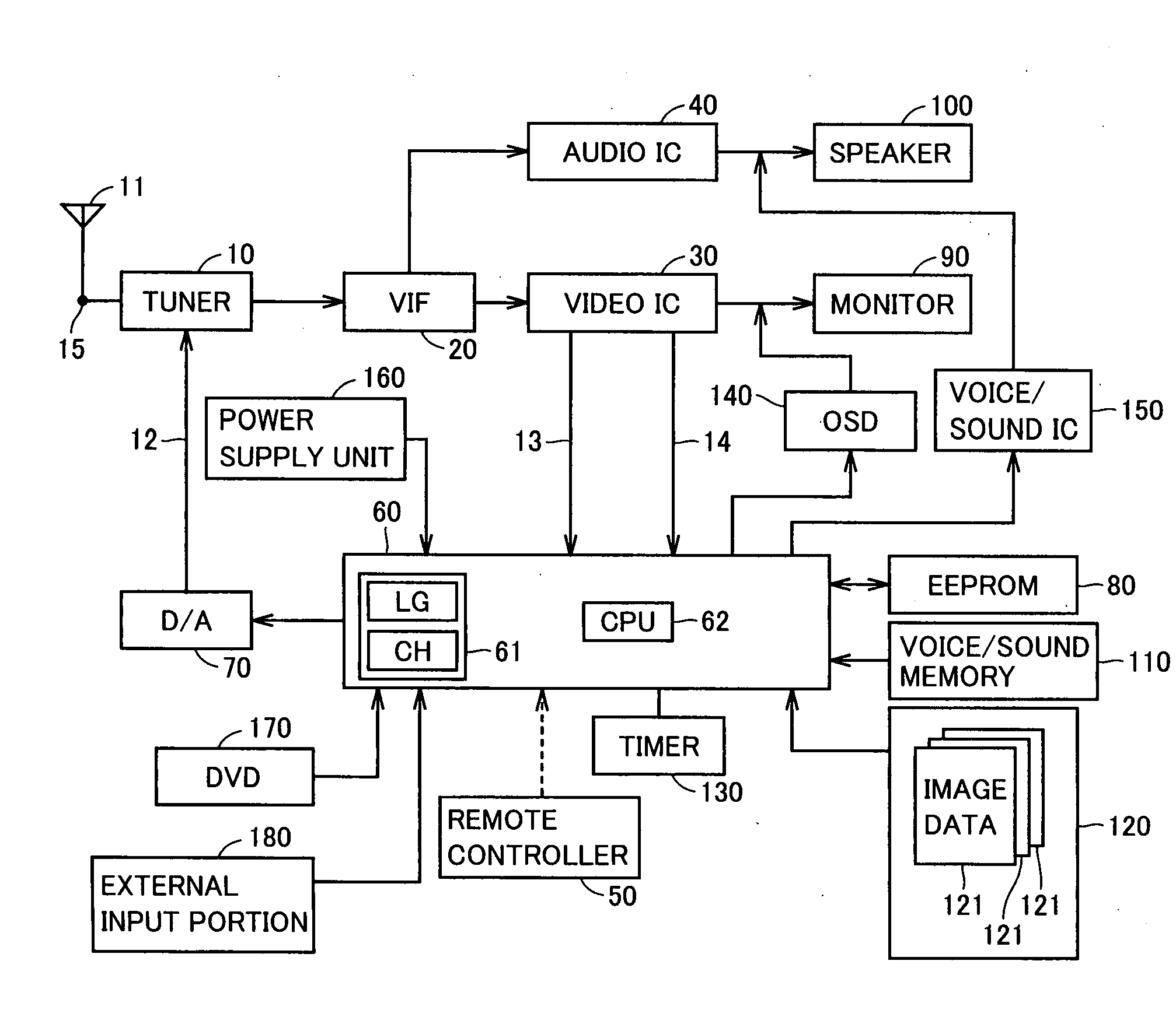
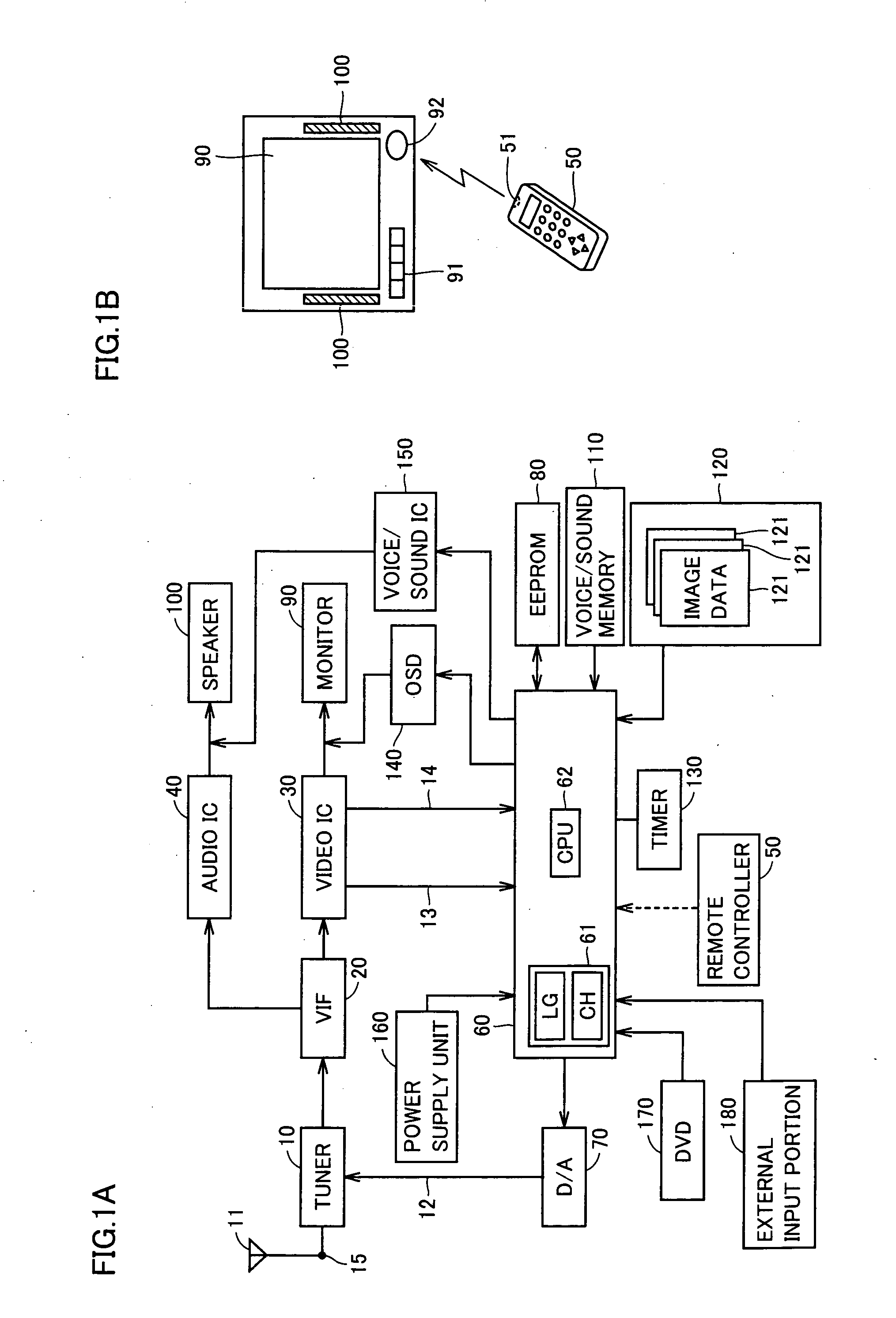
[0036]FIGS. 1A and 1B illustrate a configuration of a TV receiver according to one embodiment of a broadcast signal reception apparatus of the present invention. FIG. 1A is a block diagram showing an electrical configuration and FIG. 1B shows appearance.

[0037]Referring to FIGS. 1A and 1B, an antenna 11 provided outside, a monitor 90 serving as a display portion, and a speaker 100 are connected to configure a TV receiver. Antenna 11 receives a broadcast signal transmitted from a broadcast station and outputs the broadcast signal to the TV receiver. Monitor 90 is configured with liquid crystals and the like. Monitor 90 attains a function as the display outputting an image for displaying a video image in accordance with the supplied signal.

[0038]The TV receiver includes an antenna terminal 15, a tuner 10, a VIF (Video Intermediate Frequency) circuit 20, a video IC (Integrated Circu...


PUM


Abstract

A selection operation of a designated channel for a broadcast signal received via an antenna is performed, so that the broadcast signal of the designated channel is detected and the detected broadcast signal is output to a monitor via a video IC and the like. When the power of a microcomputer is turned on (power supply is started), the microcomputer causes a tuner to perform a channel-selection operation for the channel that has been selected at the time of most recent turn-off of the power (power supply stop). As a result of the channel-selection operation, if the tuner cannot detect the broadcast signal of the channel, the microcomputer displays an image of that channel (an image where an video image is not shown) on the monitor and thereafter displays an image for notifying a user of a measure to be taken through an OSD circuit.

Description

BACKGROUND OF THE INVENTION[0001]1. Field of the Invention[0002]The present invention relates to a broadcast signal reception apparatus such as a TV (television) receiver or a DVD (Digital Versatile Disk) recorder, and more particularly to a broadcast signal reception apparatus capable of instructing a user on a measure to be taken when a video image based on a broadcast signal in a reception channel is not displayed at the time of turn-on of power.[0003]2. Description of the Background Art[0004]Conventionally, when a user purchases a broadcast signal reception apparatus such as a TV receiver, the user initially connects an antenna terminal to an antenna plug and inserts a plug of a power cord into an outlet, so as to set a state where power can be supplied from utility power source. Thereafter, the user operates a power switch and turns the power on. Thus, supply of power at an operable level to each unit in the TV receiver is started. Thereafter, when the user performs an operatio...

Claims


Application Information

Patent Timeline
IPC IPC(8): H04N5/50H04N5/44H04N7/173H04N7/16H04B1/16H04N5/445
CPCH04N5/50H04N21/42204H04N21/4882H04N21/4425H04N21/4856H04N21/4383
Inventor YAMADA, KOUJIROUMIYABE, SEIJINISHIGAKI, HIROSHIOHHASHI, NARUYUKISUZU, HIROKAZUYAMAMOTO, MANABU
Owner FUNAI ELECTRIC CO LTD
Features
  • R&D
  • Intellectual Property
  • Life Sciences
  • Materials
  • Tech Scout
  • Unparalleled Data Quality
  • Higher Quality Content
  • 60% Fewer Hallucinations
Learn More