A feeding device for craft pull tabs

A feeding device and process technology, applied in the directions of packaging, transportation and packaging, closing, etc., can solve the problems of limited use, poor versatility, and low accuracy of process pull tab flipping, and achieve strong versatility and guaranteed effectiveness. Effect

Active Publication Date: 2018-07-20
FUJIAN SBS ZIPPER SCI & TECH CO LTD
View PDF4 Cites 0 Cited by
  • Summary
  • Abstract
  • Description
  • Claims
  • Application Information

AI Technical Summary

Problems solved by technology

[0004] The invention provides a feeding device for a process pull tab to solve the shortcomings of the existing process pull tab feeding device, such as low accuracy of turning over the process pull tab, limited use, poor versatility, etc.

Method used


Image

  • A feeding device for craft pull tabs
  • A feeding device for craft pull tabs
  • A feeding device for craft pull tabs

Examples


Embodiment 1

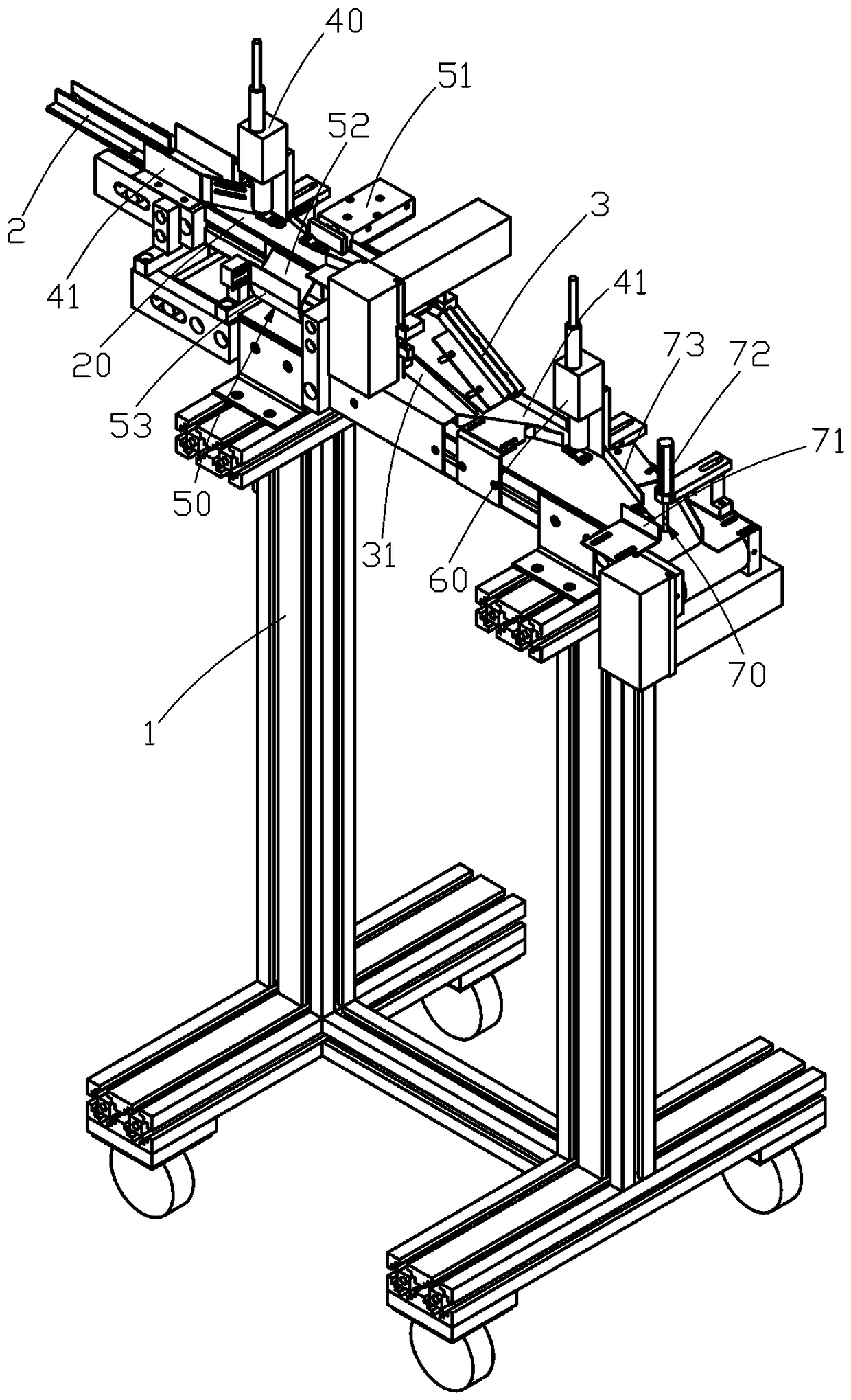
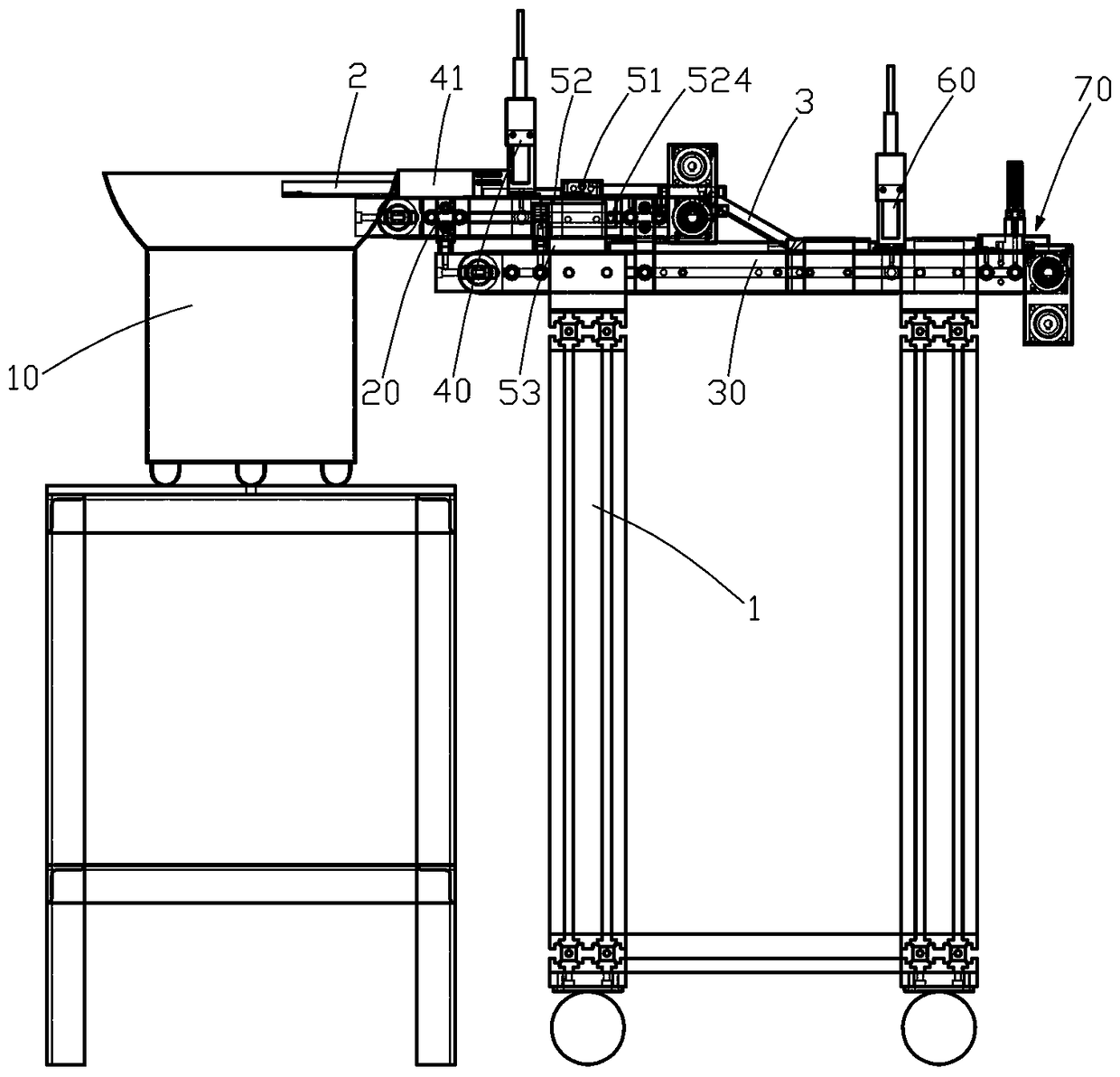
[0027] A feeding device for a craft pull tab, refer to figure 1 and figure 2 , comprising a vibration plate 10, a support frame 1, an upper conveyor 20 and a lower conveyor 30 arranged on the support frame 1, the front end of the upper conveyor 20 receives the vibration plate 10 through a transition channel 2, and the upper conveyor 20 conveys along it In the direction, the first CCD detection component 40 and the pull-tab turning mechanism 50 are arranged sequentially. The end of the upper conveyor 20 is docked with the lower conveyor 30 through an inclined channel 3, and the front end of the lower conveyor 30 is provided with a pull-tab turning mechanism. The surface turning mechanism 50 has a second CCD detection component 60 and a pulling piece turning mechanism 70 on the inclined channel 3 and the lower conveyor 30 at the end of the turning mechanism 50 . Both the front of the first CCD detection component 40 and the second CCD detection component 60 are provided with p...

Embodiment 2

[0033] refer to Figure 4 and Figure 5 , the present embodiment is different from the first embodiment except that the pull-tab U-turn mechanism is the same as the first embodiment. The pull tab turning mechanism 70 of this embodiment includes a fixed base 71, a lifting cylinder 72, a rotating cylinder 73 and a rotating box 74, the fixing base 71 is fixed on the frame of the lower conveyor 30, and the lifting cylinder 72 is fixed on the fixing base 71 side, the movable end of the lift cylinder 72 is connected to the rotary cylinder 73 through a connecting plate 721, and the movable end of the rotary cylinder 73 is connected to the rotary box 74, and between the rotary box 74 and the second CCD detection assembly 60 A pull tab material guide plate 75 is provided.

[0034] refer to Figure 5 and Figure 6 The above-mentioned rotary box 74 includes a U-shaped groove body 741 in cross section and an L-shaped cover body 742 cooperatingly arranged on the groove body 741. A hole...


PUM


Abstract

A feeding device for technological pullers comprises a vibration disk, an upper-layer conveyor and a lower-layer conveyor; a first CCD detection assembly and a puller turning-over mechanism are arranged on the upper-layer conveyor; the puller turning-over mechanism comprises a double-shaft gas cylinder and a turning-over assembly which are oppositely arranged on two side edges of the upper-layer conveyor; the turning-over assembly comprises a sliding plate and an arc-shaped supporting plate; the sliding plate comprises an inclined part and a bent part bending inwards from the tail end of the inclined part; the arc-shaped supporting plate is bent along the outer-side arc of the bent part; the tail end of the arc-shaped supporting plate extends downwards to the lower-layer conveyor; a turned puller conveying channel for supporting the puller turning-over mechanism is arranged at the front end of the lower-layer conveyor; and a second CCD detection assembly and a puller turning-around mechanism are further sequentially arranged on the lower-layer conveyor at the tail end of an inclined channel and the tail end of the turned puller conveying channel. With the feeding device, the effectiveness of turning over of the technological pullers can be guaranteed, the turned technological pullers can fall onto the lower-layer conveyor stably, and the device is high in universality and is not limited by structures of the pullers.

Description

technical field [0001] The present invention and the field of zipper manufacturing more specifically refer to a feeding device for a pull tab. Background technique [0002] The pull tab in the existing technology distinguishes the front, back, and front and rear directions. In the existing pull tab feeding device, the front and back sides and / or the front and rear directions are often inconsistent with the assembly requirements during the conveying process of the pull tab. . When the front and back sides are inconsistent with the assembly requirements, the front and back sides of the pull tab need to be turned over. When the front and rear directions are inconsistent with the predetermined direction, the front and rear ends of the pull tab need to be reversed so that all pull tabs are in the predetermined direction. [0003] The traditional method is to manually put the pull tab into the adjustable pull tab track for assembly, or after the pull tab is transported to the pus...

Claims


Application Information

Patent Timeline
Patent Type & Authority Patents(China)
IPC IPC(8): B65G47/248B65D47/24
CPCB65D47/24B65G47/248
Inventor 魏开铧朱松峰张田
Owner FUJIAN SBS ZIPPER SCI & TECH CO LTD
Why Eureka
Try Eureka