
Drive arrangement for motorized movement of a motor vehicle door or the like

a technology for motor vehicles and drive arrangements, which is applied in the direction of door/window fittings, power supplies, constructions, etc., can solve the problems of insufficient emergency operation reliability of this drive arrangement, the inability to fully meet current requirements. , to achieve the effect of reducing the length of the spindle-spindle nut gear, reducing the necessary extension, and increasing the width of the drive arrangemen

Inactive Publication Date: 2007-08-02
BROSE SCHLIESSSYSTEME GMBH & CO KG
View PDF30 Cites 33 Cited by
  • Summary
  • Abstract
  • Description
  • Claims
  • Application Information

AI Technical Summary

Benefits of technology

[0011] In accordance with the invention, the drive arrangement allows a clutch to be moved into an engaged state and into a released state. In addition, the clutch can be moved into an intermediate engaged state with reduced transmission moment and with reduced transmission force. So, the vehicle door with the clutch in the intermediate engaged state is kept in its current position at any time by the self-locking motor unit, but can be moved by manual actuation with a predetermined minimum actuating force.
[0014] Furthermore, the configuration of the gearing as a spindle-spindle nut gear is proposed. In this case, it has been found that suitable design of the spindle-spindle nut gear can be determined by tests with respect to the spindle pitch and the materials used in the spindle-spindle nut gear, so that the intermediate engaged state can also be easily implemented.
[0015] In accordance with preferred embodiments of the invention, the spindle-spindle nut gear is specially configured, specifically in the manner of a telescoping jib. In this connection, at least one telescoping sleeve is switched between the spindle and the spindle nut, by which the outside thread of the spindle can be lengthened to a certain extent. Alternatively, the inside thread of the spindle nut can be lengthened by the telescoping sleeve or sleeves. With the aforementioned integration of the telescoping sleeve or sleeves into the spindle-spindle nut gear, a reduction in the length of the spindle-spindle nut gear in the retracted state with the large advance path unchanged is possible.
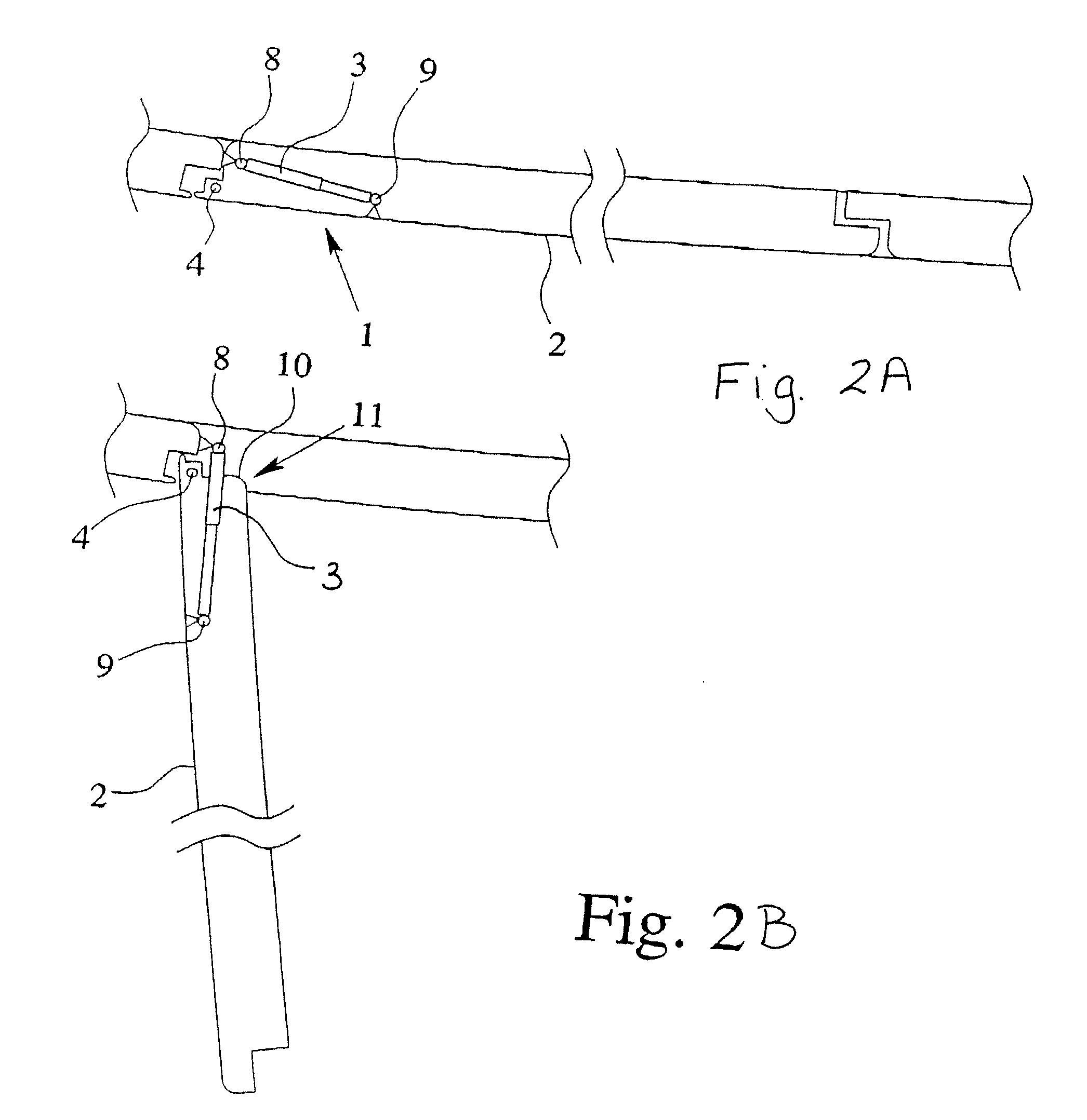
[0016] In the case of a vehicle door that is provided as a side door of a motor vehicle, the configuration of a spindle-spindle nut gear in the manner of a telescoping jib offers special advantages. Because many components are housed in a side door, the possible extension of the drive arrangement in one direction parallel to the lengthwise axis of the motor vehicle is limited. The configuration of a spindle-spindle nut gear in the manner of a telescoping jib makes it possible to greatly reduce the necessary extension in this direction. In this connection, there is an increase in the width of the drive arrangement, and therefore the extension perpendicular to the above addressed direction. For an increase in this direction, generally there is the necessary installation space in the side door.
[0017] The invention also relates to preferred versions for the triggering and configuration of a three-stage clutch. In accordance with the invention, the clutch switches automatically into the intermediate engaged state when the control voltage fails, especially in an emergency. This prevents the vehicle door from uncontrolled slamming in an emergency, while ensuring that manual actuation is possible in any situation.

Problems solved by technology

However, in an emergency, for example when the voltage supply fails or a cable breaks, there is the danger of a malfunction of the braking.
The operating reliability of this drive arrangement in an emergency is therefore greatly limited.
The known drive arrangements do not fully meet current requirements, specifically of optimum motorized operating behavior, manual actuation capacity and optimum operating behavior in an emergency.
In particular, easy manual actuation capacity, on the one hand, and reliable operating behavior in an emergency, on the other hand, impose contradictory requirements on the drive arrangement, which no existing drive arrangement satisfies at the same time.
With respect to use of spindle-spindle nut gears, one reason these requirements have not been met is that the spindle-spindle nut gears that have been available to date have established limits, especially for manual actuation capacity.
Depending on the spindle pitch, jamming can easily occur, especially when the spindle is braked.

Method used


Image

  • Drive arrangement for motorized movement of a motor vehicle door or the like
  • Drive arrangement for motorized movement of a motor vehicle door or the like
  • Drive arrangement for motorized movement of a motor vehicle door or the like

Examples


Embodiment Construction

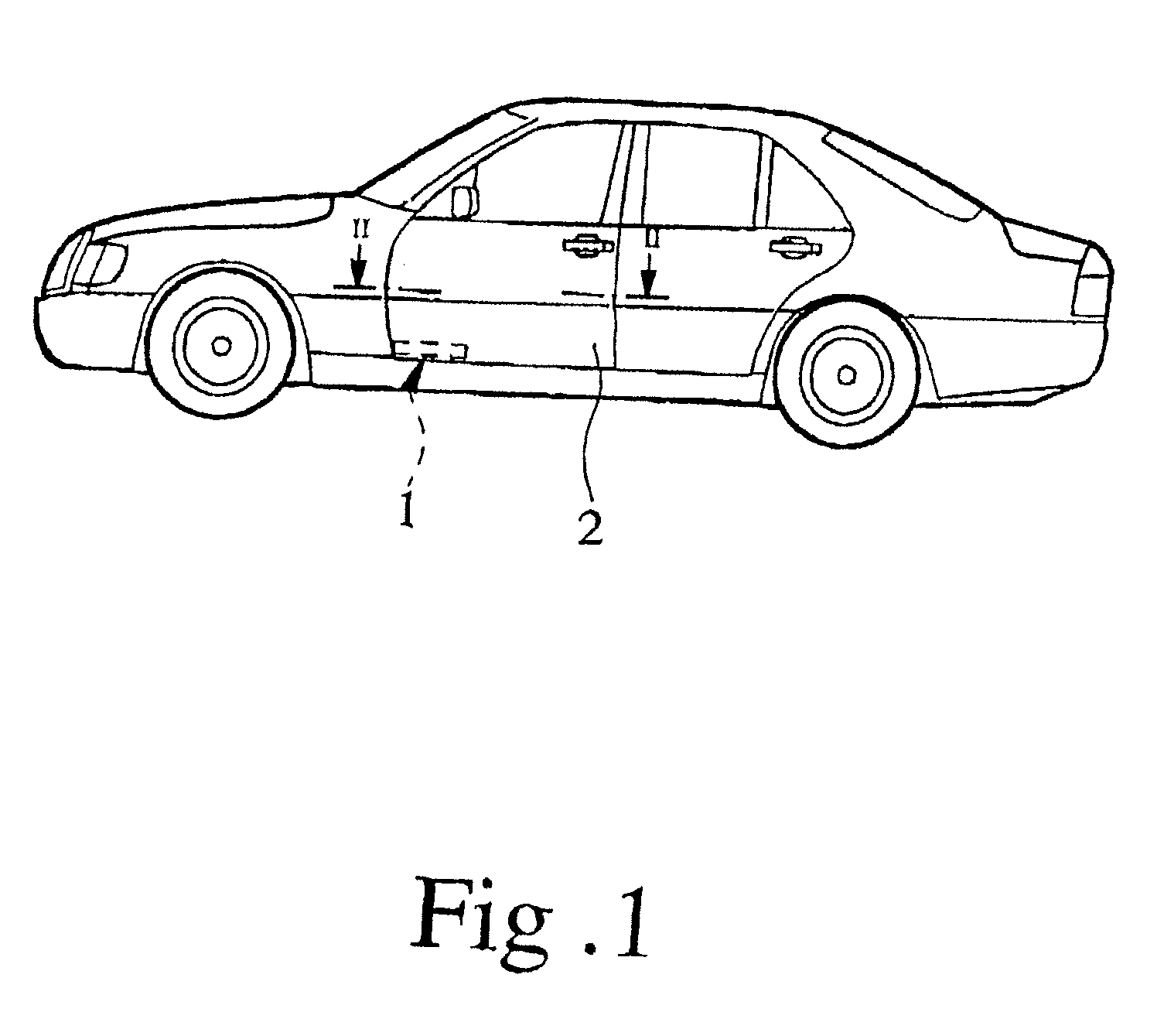
[0027] The motor vehicle shown in FIG. 1 is equipped with a drive arrangement 1 for motorized movement of a side door 2. The motor vehicle also shows a trunk lid and a hood, which can be additionally equipped with such a drive arrangement. Basically, the drive arrangement 1 in accordance with this invention can be applied to any type of access opening in a motor vehicle, including a rear hatch, a cargo space hatch or a lifting roof. When the term vehicle door is used herein, it is intended to apply to all types of vehicle doors. The side door is used herein as an exemplary embodiment.

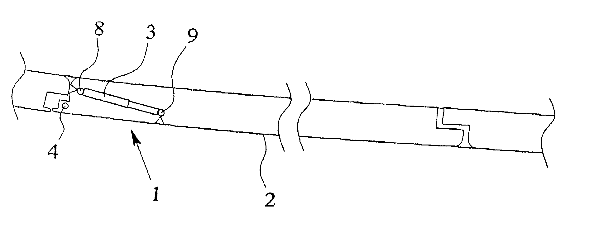
[0028] The drive arrangement 1 for motorized movement of the vehicle door 2 is equipped with at least one drive 3, seen in FIG. 3A. Preferably, a single drive 3 is provided, but more drives, such as two drives, can be provided as necessary. In the configuration of the drive arrangement 1 with two drives 3, twisting of the vehicle door 2 can be effectively opposed.

[0029] The vehicle door 2 is coupled t...


PUM


Abstract

A drive arrangement is provided for motorized pivotal movement of a vehicle door. The drive has a self-locking motor unit, a gear connected downstream of the motor unit for producing linear drive movement, and a clutch connected therebetween. The clutch can be moved into an engaged state in which the motor unit for nominal operation is engaged to the vehicle door. When the motor unit is turned off, manual movement of the vehicle door is blocked. The clutch can be moved into a released state in which the motor unit is separated from the vehicle door in terms of drive engineering. The clutch can be moved into the intermediate engaged state with reduced transmission moment and force so that the vehicle door is kept in its current position at any time by self-locking of the motor unit, but can be moved by manual actuation with a minimum actuation force.

Description

BACKGROUND OF THE INVENTION [0001] 1. Field of the Invention [0002] This invention relates to a drive arrangement for motorized movement of a motor vehicle door. [0003] 2. Discussion of Related Art [0004] The concept of a motor vehicle door disclosed herein is intended to encompass various access openings for a vehicle, including for example the side door of a motor vehicle, the rear hatch, the trunk lid, the hood, the cargo space hatch, and the roof, which may be raised or lifted. As described, the vehicle door is not included as part of the body of the vehicle. Rather, the vehicle door is coupled to the body of the motor vehicle to pivot around a pivoting axis, by which a door opening of the vehicle body can be closed. [0005] One known drive arrangement for motorized movement of a motor vehicle door is disclosed in U.S. Pat. No. 3,398,484. This drive arrangement has a drive that is equipped with a motor unit and a spindle-spindle nut gear connected downstream of the motor unit to ...

Claims


Application Information

Patent Timeline
IPC IPC(8): E05F15/02
CPCE05Y2201/236E05Y2201/246E05Y2201/25E05Y2201/462E05Y2400/612E05F15/622E05Y2201/68E05Y2400/854E05Y2400/86E05Y2201/216E05F15/611E05Y2900/531
Inventor KACHOUH, CHECRALLAH
Owner BROSE SCHLIESSSYSTEME GMBH & CO KG
Learn More