Tendon gripping device

a technology of tendon and rod, which is applied in the direction of manufacturing tools, auxiliaries of forms/shuttering/falseworks, and foundation engineering, etc., can solve the problem of wall expansion

Active Publication Date: 2007-08-02
RJD IND
View PDF22 Cites 21 Cited by
  • Summary
  • Abstract
  • Description
  • Claims
  • Application Information

AI Technical Summary

Benefits of technology

[0027] An object of the present invention is to provide a tendon gripping apparatus for gripping tendon, wherein the apparatus prevents formwork from sliding outwardly along the tendon.

Problems solved by technology

A problem typical of smooth or deformed or multiple stranded tendons is that slippage occurs, allowing the walls to expand.
The existence of springs in many gripping devices contributes to this slippage.

Method used


Image

  • Tendon gripping device
  • Tendon gripping device
  • Tendon gripping device

Examples


Embodiment Construction

[0059] The following description is provided to enable any person skilled in the art to make and use the invention and sets forth the best mode contemplated by the inventor of carrying out his invention. Various modifications, however, will readily apparent to those skilled in the art, since the generic principle of the present invention have been defined herein specifically to provide a tendon gripping device.

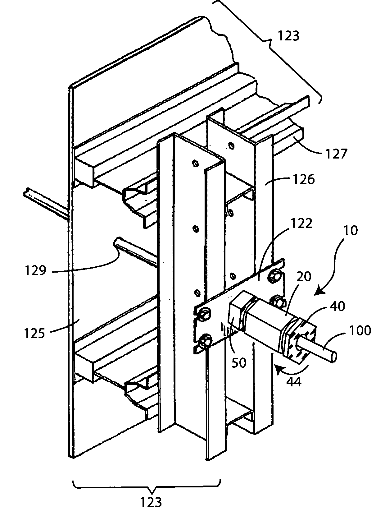
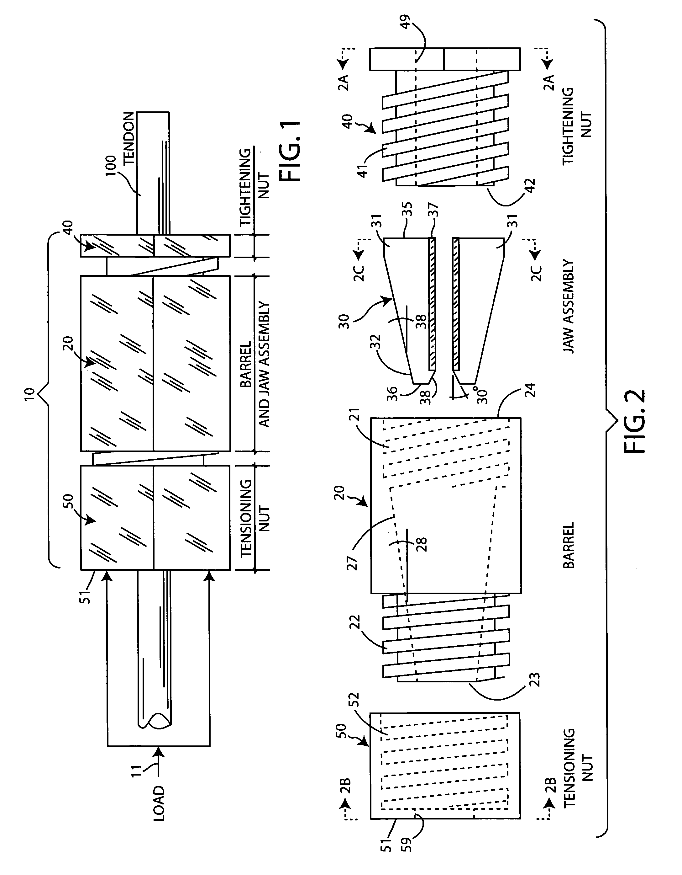
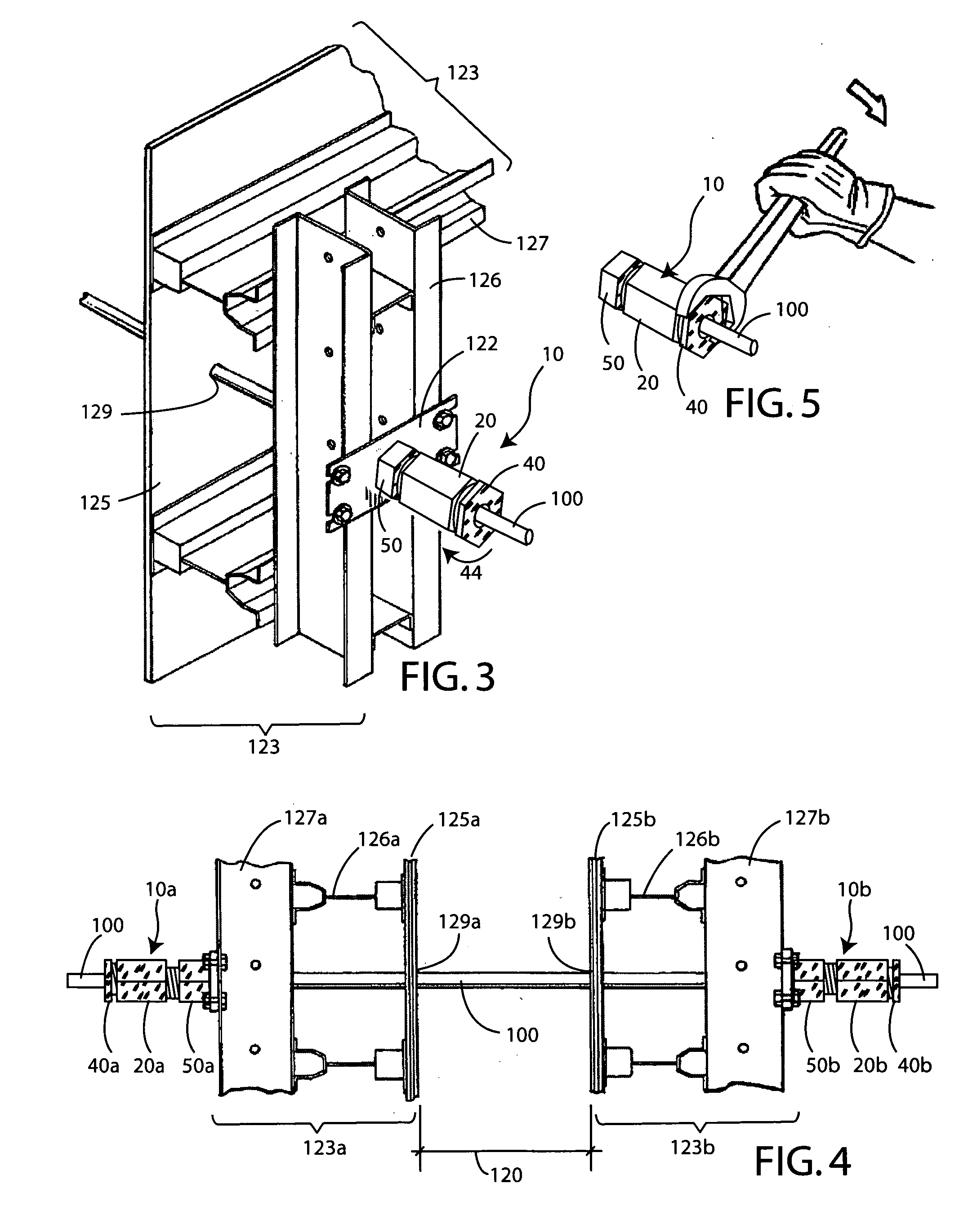
[0060]FIGS. 1 and 2 illustrate a preferred tendon gripping apparatus 10. First, for context, FIG. 1 shows a fully assembled tendon gripping apparatus 10 joined to a tendon 100. FIG. 2 is an exploded side view that shows that the preferred tendon gripping apparatus 10 comprises a housing or barrel 20, a wedge assembly 30 that fits within the barrel 20, a tightening nut 40, and a tensioning nut 50. As best shown in FIGS. 2A and 2B discussed below, the external configuration of the preferred gripping apparatus 10 is generally hexagonal in shape.

[0061] Returning to FIG. 1, one c...


PUM

PropertyMeasurementUnit
diameteraaaaaaaaaa
diameteraaaaaaaaaa
diameteraaaaaaaaaa

Abstract

An apparatus for gripping smooth and/or deformed cylindrical or multiple stranded tendons (rods) commonly used in the Art of Construction, the apparatus comprising a housing (barrel), a plurality of jaws (wedges) within the housing, a tightening device to align the jaws (wedges) and to cause engagement of the jaws (wedges) to the tendon (rod), a tensioning device to properly position the apparatus. The tendon (rod) gripping apparatus includes a first aperture and a second aperture that facilitate passage of a tendon (rod) through the apparatus. The jaw (wedge) cluster comprises a plurality of elongated members, that surround the tendon (rod), are generally wedge shaped and complementary to an inner tapered wall of the housing (barrel).

Description

BACKGROUND OF THE INVENTION [0001] 1. Field of the Invention [0002] The present invention relates to a tendon (rod) gripping apparatus primarily for gripping smooth and / or deformed or multiple stranded tendons (rods), and more particularly, to an apparatus including a housing (barrel) for receiving a tendon (rod), a plurality of elongated jaw (wedge) members, a partially externally threaded cylindrical tube device to tighten and align the jaws (wedges) and to cause initial engagement of the jaws (wedges) to the tendon (rod) by wedging the jaws (wedges) within the housing (barrel) between the tendon (rod) and inner wall of the housing (barrel), a partially internally threaded tensioning device to properly position the apparatus. [0003] As used herein, the term tendon is interchangeable with the term rod. Tendons (rods) are primarily a tensile unit when used in the Art of Construction, meaning that forces are induced normal to the longitudinal axis of the tendon (rod). [0004] Tendons ...

Claims


Application Information

Patent Timeline
Patent Type & Authority Applications(United States)
IPC IPC(8): E04C5/08
CPCE02D5/808E04C5/122E04C5/127Y10T24/3978Y10T29/53943Y10T29/53835Y10T29/53909E04G17/0651
Inventor MCCALLION, JAMES P.
Owner RJD IND
Why Eureka
Try Eureka