
Positive lubrication of a meshing gear

a technology of gear lubrication and meshing, which is applied in the direction of gear details, machines/engines, mechanical apparatus, etc., can solve the problems of gear tooth failure, gear tooth cracking, heat, etc., and achieve the effect of reducing the possibility of cracking, and reducing the possibility of gear tooth breaking o

Inactive Publication Date: 2007-08-02
HONEYWELL INT INC
View PDF15 Cites 20 Cited by
  • Summary
  • Abstract
  • Description
  • Claims
  • Application Information

AI Technical Summary

Problems solved by technology

Insufficient lubrication between meshing gears can cause scoring, micropitting, and other forms of wear and damage to the involute profile of the gear teeth, leading to higher vibration, noise, heat, and ultimately gear tooth failure.
This can exacerbate the possibility of a crack developing and the gear tooth breaking off.
Attempts at providing lubrication to a lower stress point of each of the gear teeth, or to a location that is distant from the maximum stress point of the gear teeth, has not been achieved.

Method used


Image

  • Positive lubrication of a meshing gear
  • Positive lubrication of a meshing gear
  • Positive lubrication of a meshing gear

Examples


Embodiment Construction

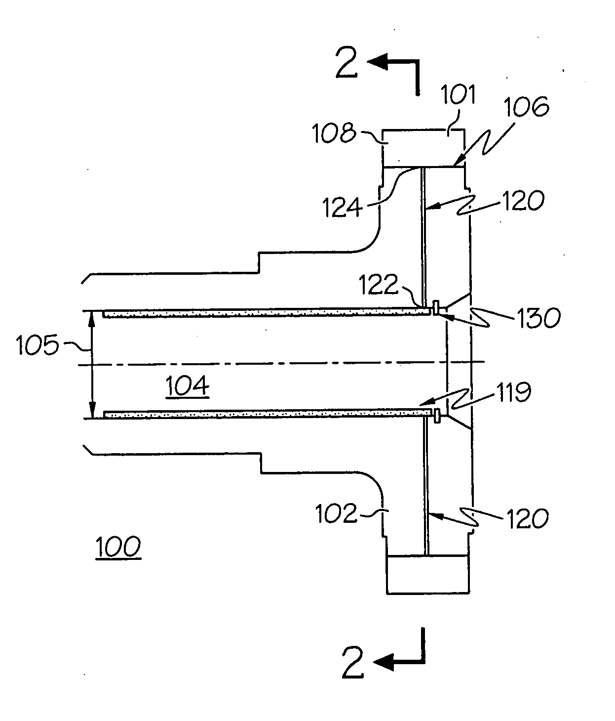
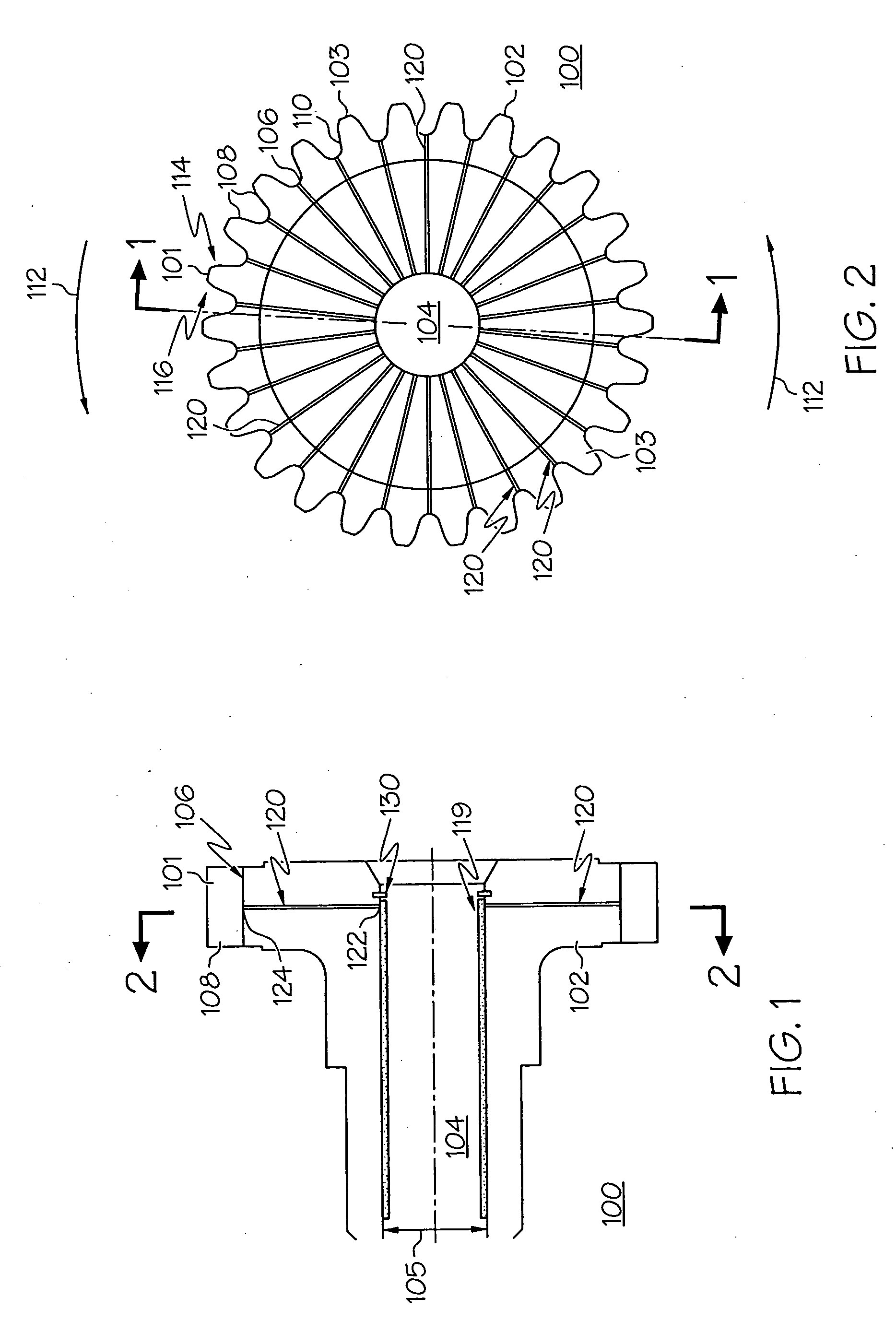
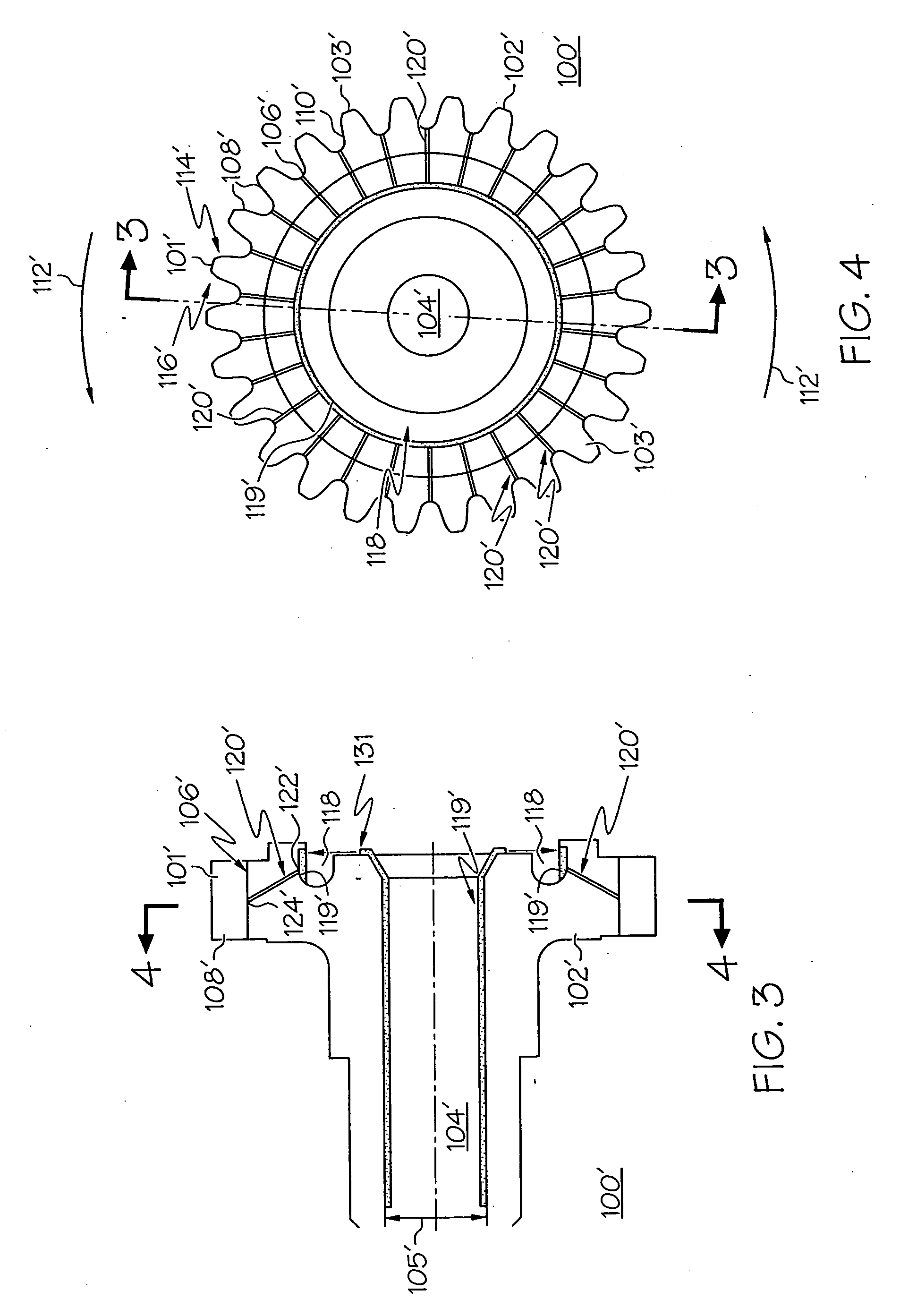
[0018] The present invention employs a means for applying a lubricant to the involute profile of a tooth on a meshing gear via a point of low stress in the tooth root of the gear. The device and method provide for the positive lubrication and maintenance of a lubricating film in meshing gears. Referring now to FIGS. 1 and 2 illustrated is a portion of a gear 100, and more particularly a toothed wheel 102, mounted on a shaft 104, sometimes referred to as a gear assembly. The assembly may be one single piece of hardware, but is hereinafter referred to as an assembly. The shaft 104 is configured, upon receipt of a suitable drive force, to rotate. The shaft 104 may simply be a bore of the gear assembly. Furthermore, The drive force may be applied either to the shaft 104, which in turn causes the toothed wheel 102 to rotate, or it may be applied to the toothed wheel 102, which causes the shaft 104 to rotate. Toothed wheel 102 includes a plurality of meshing teeth 103 each comprised of a ...


PUM


Abstract

A device and method for the lubrication of teeth in a meshing gear. A plurality of teeth are formed about a periphery of a toothed wheel. Each tooth is defined by a root portion, an involute profile portion, and a minimal stress portion. The device and method includes the formation of a plurality of fluidic passages, each including an inlet and an outlet, in fluidic communication with a lubricant and the minimal stress portion of at least one of the plurality of teeth. During operation, the lubricant contained flows via centrifugal force to the minimal stress portion of each of the plurality of teeth via the fluidic passages. The fabrication of the outlet of the fluidic passages at a minimal stress portion of at least one of the plurality of teeth eliminates any further stress fabrication on the portion of the tooth structure that is under stress during operation.

Description

FIELD OF THE INVENTION [0001] The present invention relates to the lubrication of gears. More particularly, the present invention relates to the lubrication of toothed meshing gears. BACKGROUND OF THE INVENTION [0002] It is well known to dispose meshing gears in a lubricant filled case. The lubricant, which may be either solid or liquid, bathes the gears, creating a lubricating field that maintains gear lubrication. Alternative means of lubricating meshing gears have been used, such as through the use of a static oil jet mounted on the gearbox structure that disperses lubricant onto the meshing teeth. Oil jet dispersion typically is achieved in one of two ways: as an into-mesh jet where oil is dispersed onto the teeth prior to meshing, or as an out-of-mesh jet where lubricant is dispersed onto the teeth as they complete the mesh. In addition, a cooling oil splash or mist has been used to lubricate meshing gears in which high speed components churn oil spray through a gearbox space. ...

Claims


Application Information

Patent Timeline
IPC IPC(8): F16H57/04F01M1/12
CPCF16H57/0427F16H57/0493F16H57/0431
Inventor SHILO, MARK A.MEACHAM, WALTER L.ZADIK, JOHN T.
Owner HONEYWELL INT INC
Learn More