Redundant automation system comprising a master and a standby automation device

Inactive Publication Date: 2007-08-02
SIEMENS AG
View PDF10 Cites 11 Cited by
  • Summary
  • Abstract
  • Description
  • Claims
  • Application Information

AI Technical Summary

Benefits of technology

[0040] This makes it possible to implement the inventive redundant automation system in a thoroughly cost-effective manner, in which case it is possible to profit from the fast pace of development of performance of the said standard PC components. In addition it is easy to procure spares for the system or to expand the devices by additional components.
[0041] One advantage common to all the stated embodiments lies particularly in the fact that th

Problems solved by technology

A failure of these automation systems inevitably leads to a fault in the technical execution and thereby for example to a failure of production of goods or energy.
These types of automation solution require a major financial investment since the known systems are highly specialized and technically very complex and thus also very expensive.
Errors which can occur during the control of a technical process with regard to the automation systems on the one hand relate to the control software running on the automation devices, but on the other hand also relate to the hardware components used.
As regards the last-mentioned errors, problems do not usually arise as a result of a total failure of an automation device, but as a result of static and/or sporadic faults of individual hardware components of the automation devices.
In such cases output signals then occur as a result relating to the faulty automation device, which although present and thus theoretically also able to

Method used


Image

  • Redundant automation system comprising a master and a standby automation device
  • Redundant automation system comprising a master and a standby automation device

Examples


Example

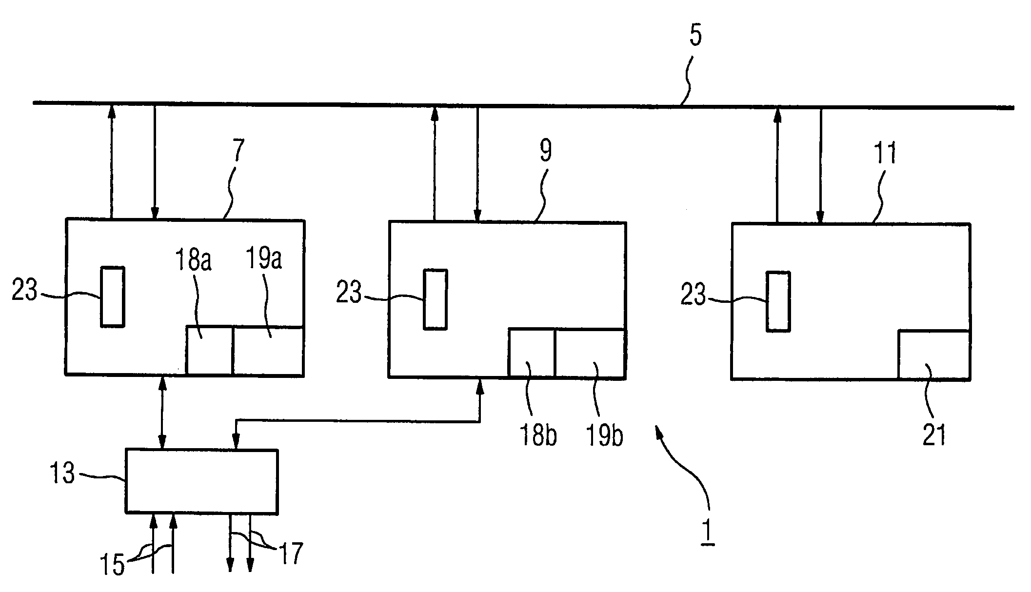
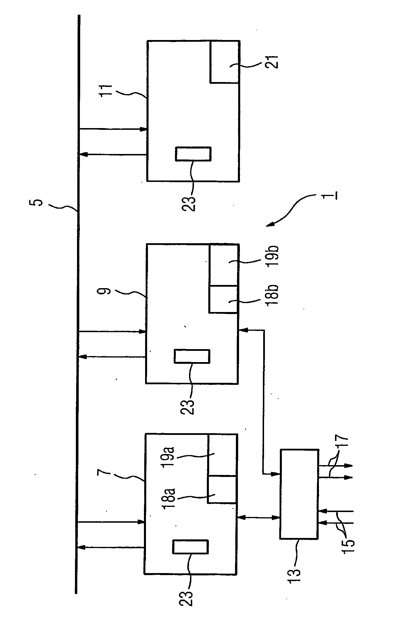
[0045] The FIGURE shows a redundant automation system 1 in accordance with the invention, comprising a master automation device 7 and a standby automation device 9.

[0046] A computer-aided monitoring device 11 is assigned to the said devices.

[0047] A communication link 5 is provided for a rapid exchange of data between the devices 7, 9, 11.

[0048] The redundant automation system 1 is used to control a technical process not shown in any greater detail.

[0049] Process data 15 is recorded by the technical process by means of a process periphery 13 which comprises input and output means, and output signals 17 are issued to the process. Process data 15 is for example also referred to as process input signals or input signals.

[0050] The process periphery 13 is connected to both the master automation device 7 and also to the standby automation device 9. A connection between the process periphery 13 and the monitoring device 11 is not provided and is also not required, since in accordance...


PUM


Abstract

The invention concerns a redundant computerizing system comprising additionally to a master programmable automaton and a standby programmable automaton, a computerized monitoring device enabling a memory image of the comparison process concerning a certain number of output signals of the computerizing system to be set up.

Description

CROSS REFERENCE TO RELATED APPLICATIONS [0001] This application is the US National Stage of International Application No. PCT / EP2005 / 051782, filed Apr. 21, 2005 and claims the benefits of European Patent application No. 04009999.6 filed Apr. 27, 2004. All of the applications are incorporated by reference herein in their entirety.FIELD OF INVENTION [0002] The invention relates to a redundant automation system for controlling a technical process. BACKGROUND OF THE INVENTION [0003] In many industrial applications automation systems are used for controlling technical processes. A failure of these automation systems inevitably leads to a fault in the technical execution and thereby for example to a failure of production of goods or energy. [0004] To prevent an interruption of the production process the use of so-called high-availability automation devices based on Programmable Logic Controllers within the framework of the automation system is known, with the automation devices being dupl...

Claims


Application Information

Patent Timeline
IPC IPC(8): G05B23/02G05B19/05
CPCG05B19/058
Inventor HUMPERT, HANS-DIETERKLEYER, DIETER
Owner SIEMENS AG
Why Eureka
Try Eureka