Seal device with sensor and rolling bearing device using the seal device

a technology of sealing device and roller bearing, which is applied in the direction of mechanical equipment, instruments, transportation and packaging, etc., can solve the problems of difficult application to the hub unit of the automobile, achieve the effect of reducing the dimension in the axial direction of the roller bearing device with the sensor, and facilitating the assembly of the sensor to the roller bearing

Inactive Publication Date: 2007-08-02
JTEKT CORP +2
View PDF6 Cites 10 Cited by
  • Summary
  • Abstract
  • Description
  • Claims
  • Application Information

AI Technical Summary

Benefits of technology

[0006] The present invention aims to provide a seal device with sensor in which the sensor is resin molded to the core metal configuring the seal device thereby suppressing the dimension in the axial direction of the seal device with sensor and the roller bearing device and preventing the core metal and the resin from separating and the moisture from entering from the interface of the core metal and the resin, and a roller bearing device using the same.

Problems solved by technology

In applying this type of roller bearing device to the hub unit of an automobile, the dimension in the axial direction must be suppressed to less than or equal to a predetermined value, but the ring shaped magnet and the sensor supporting member are projected more in the axial direction than the bearing device in patent article 1 thereby making the application to the hub unit of the automobile difficult.

Method used


Image

  • Seal device with sensor and rolling bearing device using the seal device
  • Seal device with sensor and rolling bearing device using the seal device
  • Seal device with sensor and rolling bearing device using the seal device

Examples


first embodiment

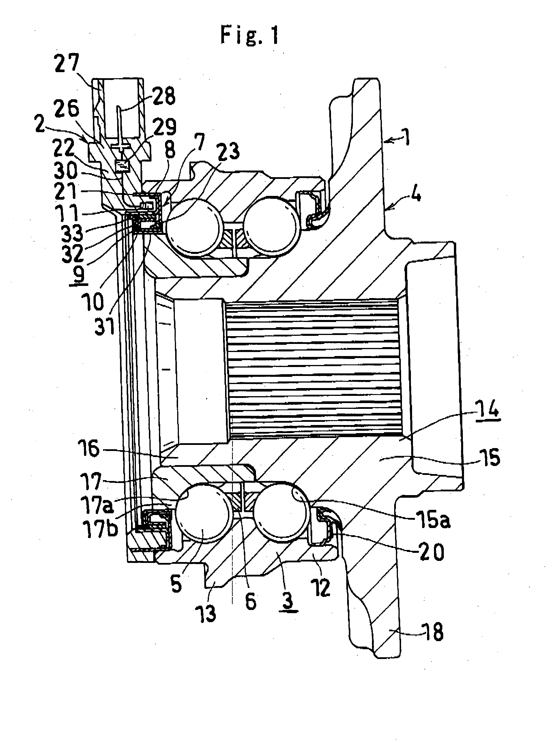
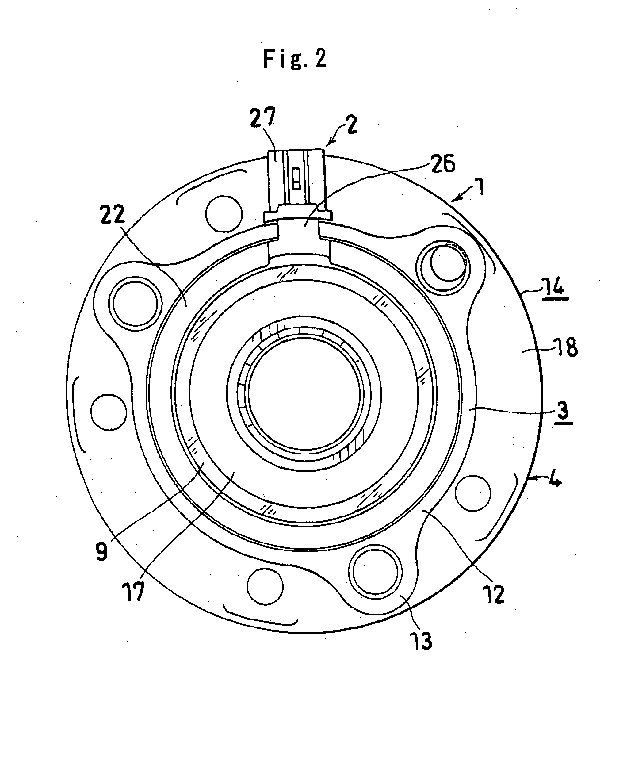
[0039]FIG. 1 to FIG. 3 show a seal device with sensor and a roller bearing device using the same of the present invention. In the following description, left and right corresponds to left and right of FIG. 1. Further, left is the internal side of the vehicle, and right is the external side of the vehicle.

[0040] The roller bearing device includes a hub unit (1), a sensor device (2) arranged therein, and a pulser (10) serving as a detected section.

[0041] The hub unit (1) includes a vehicle body side raceway member (3) fixed on the vehicle body side, a wheel side raceway member (4) to where a wheel is attached, balls (5) serving as a plurality of rollers arranged in two columns between the members (3), (4), and a holder (6) for holding the ball (5) of each column.

[0042] The vehicle body side raceway member (3) includes a cylindrical part (12) with an outer ring (fixed ring) function of the bearing and having two columns of outer ring raceway formed on the inner peripheral surface, an...

third embodiment

[0073]FIG. 6 and FIG. 7 show the seal device with sensor and the roller bearing device using the same according to the present invention. FIG. 6 corresponds to FIG. 2, FIG. 7 corresponds to FIG. 4, and the same reference characters are denoted for the same configuration, and the explanation thereof is omitted.

[0074] As described above, since the outer end part in the axial direction of the fitting cylindrical part (61) of the core metal (21) is insert molded so as to be positioned in the resin, the resin member (22) includes a resin portion exposed from the core metal (21). In the present embodiment, a plurality of (four in the figure) convex parts (57) (58) are arranged in the circumferential direction at a predetermined interval at the outer surface (22b) and the inner surface (22c) in the axial direction of the resin portion exposed from the core metal (21). A plurality of convex parts (57) (58) are integrally formed in the resin member (22) during insert molding so as to be arra...

second embodiment

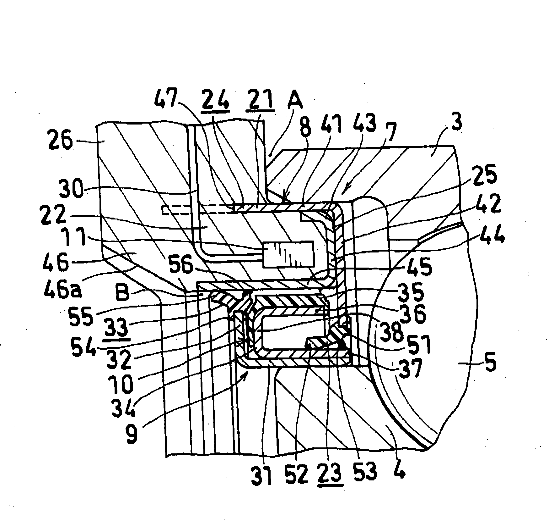
[0077] The core metal (21) of the fixed side seal member (8) has a shape similar to that of the second embodiment, includes a fitting cylindrical part (61) fitted and fixed to the left end part of the vehicle body side raceway member (3), a coupling part (62) extending inward (direction towards the wheel side raceway member (4)) in continuation with the inner end part (right end part) in the axial direction of the cylindrical part (61), a moisture entering prevention cylindrical part (63) extending outward (towards left) in the axial direction in continuation with the coupling part (62), and an inward flange part (64) extending inward in continuation with the moisture entering prevention cylindrical part (63), and has the elastic seal (65) adhered to the inner peripheral edge of the inward flange part (64). The left part of the fitting cylindrical part (61) is projected more towards the left than the left end of the vehicle body side raceway member (3) and inserted into the resin me...


PUM


Abstract

A seal device with sensor (7) is configured by a fixed side seal member (8) fixed to a vehicle body side raceway member (3) and a rotating side seal member (9) fixed to a wheel side raceway member (4). The fixed side seal member (8) includes a core metal (21), a resin member (22) integrated with the core metal (21) through insert molding, a sensor (11) resin molded to the core metal (21), and an elastic seal (65) adhered to the core metal (21). The core metal (21) of the fixed side seal member (8) includes a fitting cylindrical part (61) fitted and fixed to the vehicle body side raceway member (3), a coupling part (62) extending towards the cylindrical part (31) of the rotating side seal member (9) and a moisture entering prevention cylindrical part (65) extending outward in the axial direction in continuation with the coupling part (62), and the outer end part in the axial direction of the fitting cylindrical part (61) is positioned in the resin (22).

Description

TECHNICAL FIELD [0001] The present invention relates to a seal device with sensor and a roller bearing device using the same. BACKGROUND ART [0002] In automobiles, since various information are necessary to perform control, arranging a sensor device in a hub unit (roller bearing device) including a wheel side raceway member to where a wheel is attached, a vehicle body side raceway member fixed on the vehicle body side, and two columns of rollers arranged between the two raceway members has been proposed. [0003] As such roller bearing device, that including an outer ring, an inner ring, rollers arranged between the rings, and a seal arranged between the ends of both rings, wherein a sensor supporting member arranged with the sensor is attached to the end face of the outer ring, and a ring shaped magnet is fixed on the outer surface in the axial direction of a slinger fixed to the inner ring is disclosed in patent article 1 (Japanese Patent Publication No. 5-26233). [0004] In applying...

Claims


Application Information

Patent Timeline
Patent Type & Authority Applications(United States)
IPC IPC(8): F16C41/04F16C19/18F16C19/52F16C33/78F16J15/32G01P3/44
CPCF16C19/186F16C33/78G01P3/443F16C2326/02F16J15/326F16C41/007
Inventor KOYAGI, KATSURANUMATA, TETSUAKIINOUE, MASAHIROMATSUI, SYUNICHISHIGE, YOSHIFUMIKUWAJIMA, TOORUKIMURA, MASAHIROIWASE, EIICHIROKAGEYAMA, TAKESHI
Owner JTEKT CORP
Why Eureka
Try Eureka