Barrier orifice valve for gas lift

a barrier orifice valve and lift technology, which is applied in the direction of machines/engines, wellbore/well accessories, sealing/packing, etc., can solve the problems of slow production rate, insufficient pressure, seal failure and leakage, etc., and achieve the effect of preventing backflow and optimizing flow ra

Active Publication Date: 2007-08-09
BAKER HUGHES INC
View PDF8 Cites 77 Cited by
  • Summary
  • Abstract
  • Description
  • Claims
  • Application Information

AI Technical Summary

Benefits of technology

[0009] In described embodiments, the flapper members may be emplaced in either an externally-mounted gas lift valve or within a side-pocket mandrel integrated into the production tubing string. In further aspects of the invention, multiple barrier orifice valves may be used to optimize flow rates or to prevent backflow to another gas lift valve.

Problems solved by technology

This pressure is sometimes sufficient to lift oil within the wellbore to the surface for production.
Sometimes, however, the formation pressure is not sufficient, and, even under the impetus of surface pumps, the rate of production is slow.
Unfortunately, many conventional gas lift valve designs are prone to wear and damage during operation that can lead to seal failure and leakage over time.

Method used


Image

  • Barrier orifice valve for gas lift
  • Barrier orifice valve for gas lift
  • Barrier orifice valve for gas lift

Examples


Embodiment Construction

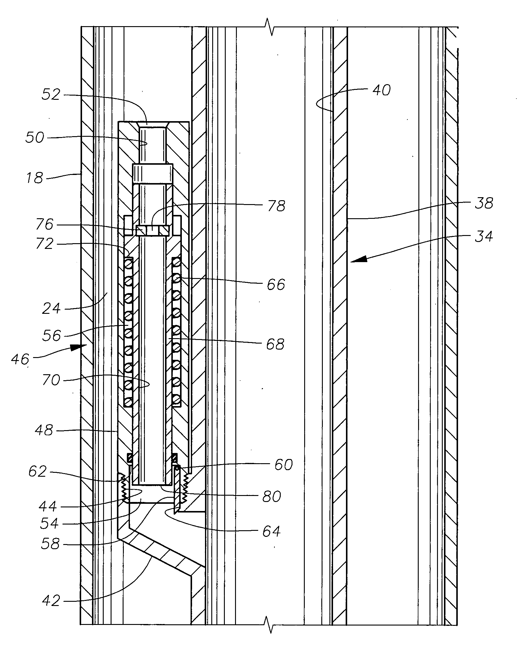
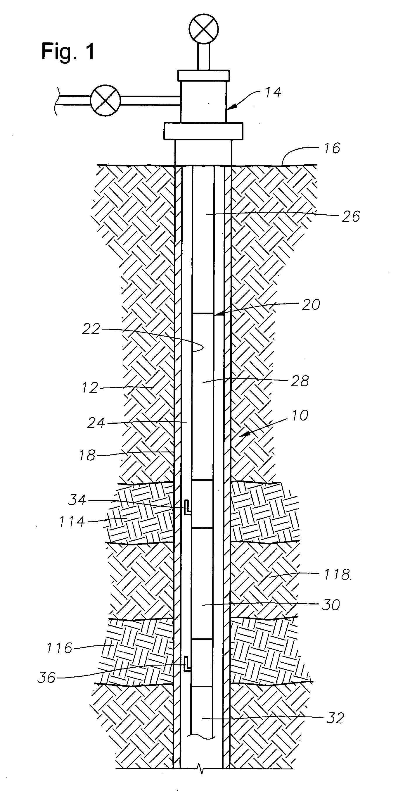
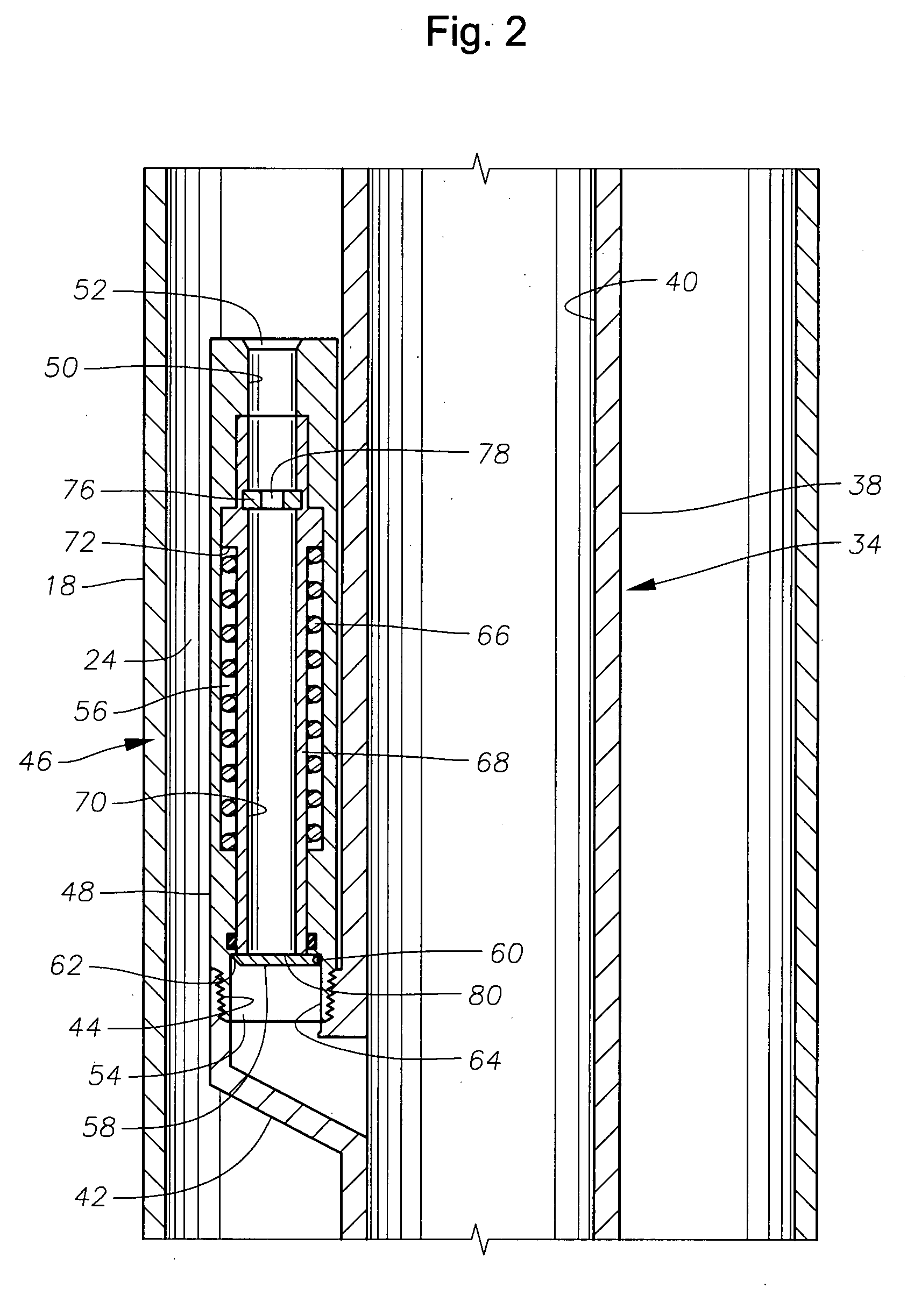
[0018]FIG. 1 illustrates an exemplary subterranean wellbore 10 passing through the earth 12 from a wellhead 14 at the surface 16. The wellbore 10 is lined with casing 18, as is known in the art. A production tubing string 20 is disposed within the wellbore 10 from the wellhead 14 and defines an axial flowbore 22 along its length. As those of skill in the art will understand, the production tubing string 20 extends downwardly to sets of production nipples or other production arrangements (not shown) for obtaining hydrocarbons from a surrounding formation. An annulus 24 is defined between the production tubing string 20 and the casing 18.

[0019] The production tubing string 20 is made up of a number of production tubing sections 26, 28, 30, 32 that are secured in an end-to-end fashion with one another by threaded connection. Alternatively, the production tubing string 20 may be made up of coiled tubing that has been deployed from the surface 16 in a manner known in the art. Incorporat...


PUM


Abstract

Gas lift valve designs and gas lift systems are described that feature a positive closure mechanism that is highly resistant to significant wear or damage that would result in fluid leakage. A pivotable flapper member is incorporated into a gas lift valve and used as a flow control mechanism. The flapper member provides a positive barrier to fluid flow from the production tubing to the annulus, even after substantial wear or damage.

Description

BACKGROUND OF THE INVENTION [0001] 1. Field of the Invention [0002] The invention relates generally to gas lift arrangements used for enhanced recovery of hydrocarbons. In particular aspects, the invention relates to the construction and operation of gas lift valves used in hydrocarbon-producing wellbores. [0003] 2. Description of the Related Art [0004] The flow of fluids into a wellbore from a surrounding subterranean reservoir often occurs as a result of natural formation pressure. This pressure is sometimes sufficient to lift oil within the wellbore to the surface for production. Sometimes, however, the formation pressure is not sufficient, and, even under the impetus of surface pumps, the rate of production is slow. In this case, techniques can be used to help improve the rate of production. One well-known technique for enhancing the rate of production is known as artificial lift, or gas lift. Gas lift valves are incorporated into the production tubing string and are used to flo...

Claims


Application Information

Patent Timeline
Patent Type & Authority Applications(United States)
IPC IPC(8): E21B43/00
CPCE21B43/123Y10T137/2934
Inventor KRITZLER, JAMES H.HOLT, JAMES H.RANDAZZO, VICCHAPMAN, WALT R.
Owner BAKER HUGHES INC
Why Eureka
Try Eureka