Food waste reduction mechanism for disposer

a technology of food waste and reduction mechanism, which is applied in the direction of water installations, solid separation, construction, etc., can solve the problems of stringy food waste that cannot be adequately reduced in size, the design of the reduction mechanism in the disposer may encounter some difficulty in sufficiently reducing fibrous, stringy, elastic food waste, etc., and achieves the effect of reducing food waste, reducing food waste, and reducing food was

Inactive Publication Date: 2007-08-09
EMERSON ELECTRIC CO
View PDF41 Cites 6 Cited by
  • Summary
  • Abstract
  • Description
  • Claims
  • Application Information

AI Technical Summary

Benefits of technology

[0008] In one embodiment of the disclosed reductiori mechanism, a rotatable plate is coupled to a shaft of a motor housed in the disposer. A stationary plate is disposed adjacent the rotatable plate and defines a plurality of apertures therethrough. The stationary plate has a central opening. The rotatable plate is positioned for rotation within the central opening of the stationary plate. The rotatable plate has a central portion coupled to the motor shaft and has a peripheral portion disposed adjacent the central opening in the stationary plate. One or more lugs are attached to the peripheral portion of the rotatable plate and have a surface or edge for passing over the apertures in the stationary plate for shearing the food waste during operation. The lugs can be movably attached to the rotatable plate and capable of swiveling and sliding relative to the rotatable plate. Alternatively, the lugs can be fixedly attached to the rotatable plate. Moreover, a combination of fixed and movable lugs can be used on the rotatable plate. Interaction between the lugs and the apertures in the plate produce shearing or cutting forces for reducing the food waste. A stationary ring is disposed in the disposer and has an inner wall disposed about the stationary plate. The lugs attached to the rotatable plate can have ends for passing adjacent the inner wall. Interaction between the lugs and the stationary ring produce grinding or shredding forces for reducing the food waste.
[0010] In another embodiment of the disclosed reduction mechanism, a stationary ring is disposed in a housing of the disposer between the inlet and the outlet of the disposer. A rotatable plate is coupled to a motor shaft and is positioned for rotation relative to the inner wall of the stationary ring. The plate has fixed and / or movable lugs for reducing food waste with the stationary ring. Interaction between ends of the lug and the stationary ring produce grinding or shredding forces for reducing the food waste. The rotatable plate has an edge forming a gap with the stationary ring for conveying reduced food waste to the outlet. One or more cutting elements are mounted in housing of the disposer adjacent a bottom surface of the plate. Blades of the cutting elements extend adjacent the gap for cutting food waste conveyed through the gap.
[0011] In another embodiment of the disclosed reduction mechanism, a stationary ring is disposed in a housing of the disposer between the inlet and the outlet of the disposer. A rotatable plate is coupled to a motor shaft and is positioned for rotation relative to the inner wall of the stationary ring. The plate has fixed and / or movable lugs for reducing food waste with the stationary ring. Interaction between ends of the lug and the stationary ring produce grinding or shredding forces for reducing the food waste. The rotatable plate has an edge forming a gap with the stationary ring for conveying reduced food waste to the outlet. One or more cutting elements are mounted on a bottom surface of the rotatable plate. Blades of the cutting elements extend beyond the edge of the plate for reducing food waste conveyed through the gap.
[0012] In another embodiment of the disclosed reduction mechanism, a stationary ring is disposed in a housing of the disposer between the inlet and the outlet of the disposer. A rotatable plate is coupled to a first shaft of a first motor and is positioned for rotation relative to the inner wall of the stationary ring. The plate has fixed and / or movable lugs for reducing food waste with the stationary ring. Interaction between ends of the lug and the stationary ring produce grinding or shredding forces for reducing the food waste. The rotatable plate has an edge forming a gap with the stationary ring for conveying reduced food waste to the outlet. A rotatable cutting member is disposed underneath the rotatable plate and is coupled to a hollow shaft of a second motor housed in the disposer. The hollow shaft is disposed over first shaft, and the motors are housed one above the other in the housing. The shafts rotate in opposite directions. Blades on the rotatable cutting member extend beyond the edge of the rotatable plate for reducing food waste conveyed through the gap between the rotatable plate and stationary ring.
[0013] In another embodiment of the disclosed reduction mechanism, a stationary ring is disposed in a housing of the disposer between the inlet and the outlet of the disposer. A rotatable plate is coupled to a motor shaft and is positioned for rotation relative to the inner wall of the stationary ring. The plate has fixed and movable lugs for reducing food waste with the stationary ring. Interaction between ends of the lugs and the stationary ring produce grinding or shredding forces for reducing the food waste. The rotatable plate has an edge forming a gap with the stationary ring for conveying reduced food waste to the outlet. A rotatable impact member is attached to a top surface of the rotatable plate. A plurality of hooked teeth on the rotatable impact member pass by the inner wall of the stationary ring. The hooked teeth also pass by breakers fixedly attached to the rotatable plate. The rotatable impact member-can have pitched surfaces for engaging water flow that causes the rotatable impact member to rotate. A drive belt can be disposed about a shaft of the rotatable impact member and disposed about a central hub in the disposer to cause the rotatable impact member to rotate.
[0015] In another embodiment of the disclosed reduction mechanism, a rotatable plate is coupled to the shaft of the rotational source and is positioned for rotation in the housing. A first hub is mounted about the shaft. A second hub is rotatably mounted on the rotatable plate and has at least one cutting element attached thereto for reducing food waste. A drive member connects the first hub to the second hub for rotating the second hub during operation of the disposer.

Problems solved by technology

Current designs of reduction mechanisms in disposers may encounter some difficulty in sufficiently reducing fibrous, stringy, or elastic food waste, such as cornhusks, artichokes, parsley stems, poultry bones, and poultry skin, for example.
Such food waste may pass though the radial spaces between the rotatable plate and stationary ring without being adequately reduced in size.
Consequently, the passed fibrous or stringy food waste may create blockages in the disposer discharge or in the household plumbing.

Method used


Image

  • Food waste reduction mechanism for disposer
  • Food waste reduction mechanism for disposer
  • Food waste reduction mechanism for disposer

Examples


Embodiment Construction

[0030] In the interest of clarity, not all features of actual implementations of a reduction mechanism for a food waste disposer are described in the disclosure that follows. It will of course be appreciated that in the development of any such actual implementation, as in any such project, numerous engineering and design decisions must be made to achieve the developers' specific goals, e.g., compliance with mechanical and business related constraints, which will vary from one implementation to another. While attention must necessarily be paid to proper engineering and design practices for the environment in question, it should be appreciated that the development of a reduction mechanism would nevertheless be a routine undertaking for those of skill in the art given the details provided by this disclosure.

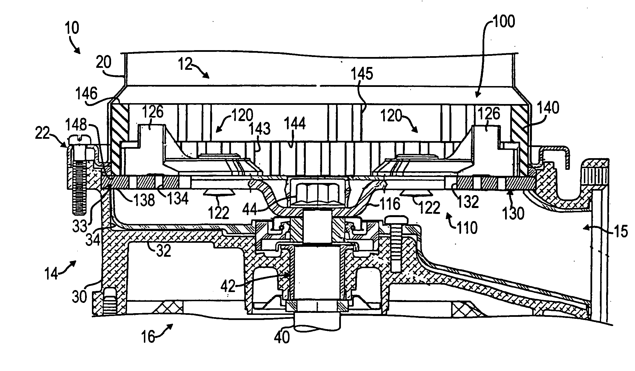
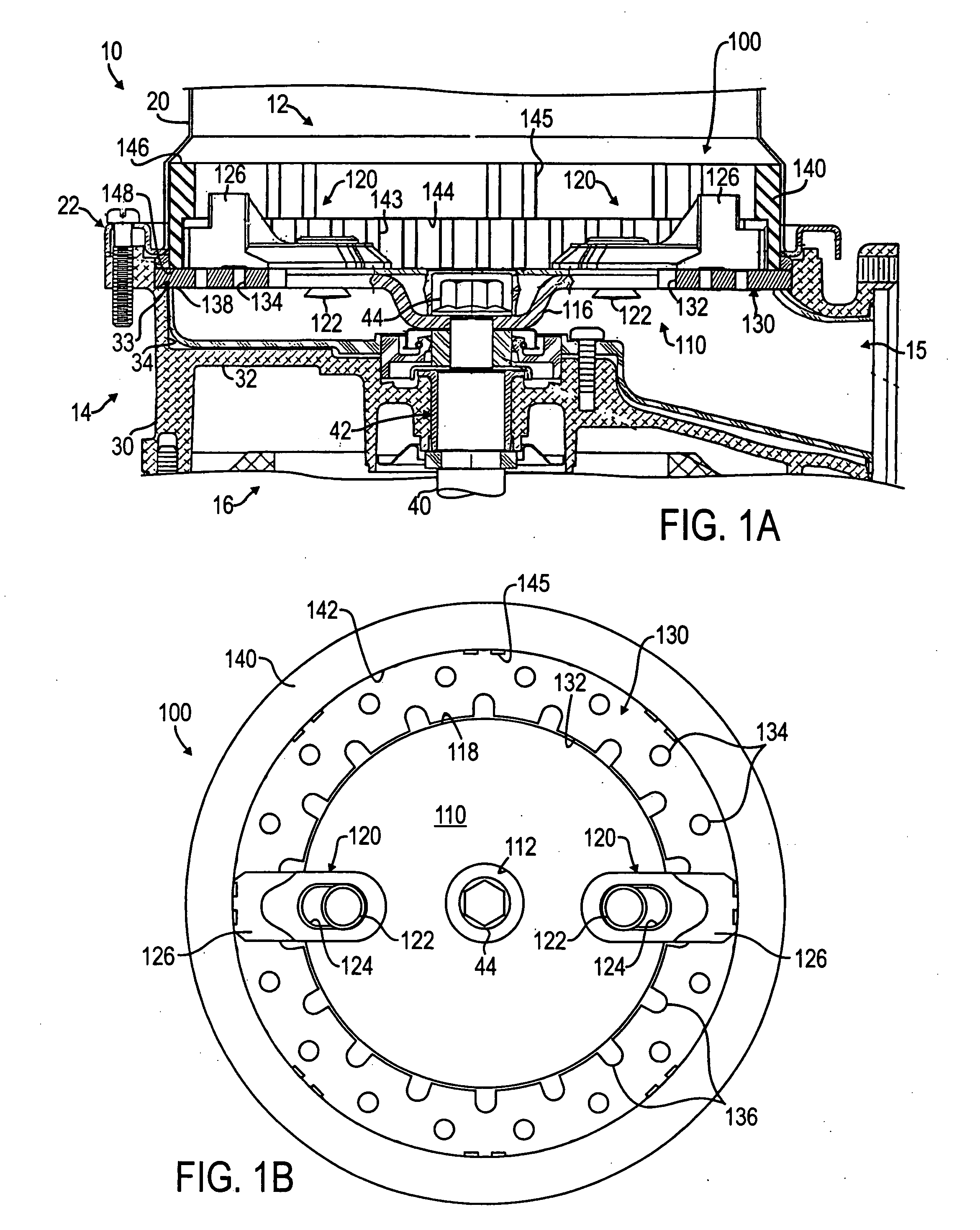
[0031] Referring to FIGS. 1A-1B, an embodiment of a reduction mechanism 100 is illustrated. FIG. 1A shows a portion of a food waste disposer 10 in side cross-section having the red...


PUM


Abstract

Various mechanisms for reducing food waste in a food waste disposer are disclosed. In each of the reduction mechanisms, structures are provided for shearing food waste as it passes through or past a rotating shredder plate of the disposer. In one embodiment, the reduction mechanism has a rotatable plate coupled to a rotational source and positioned for rotation relative to an inner wall of a stationary ring. The plate has a fixed lug attached to the rotatable plate and has a movable lug attached to the rotatable plate. In another embodiment, the reduction mechanism includes a rotatable plate coupled to a rotational source and a stationary plate disposed adjacent the rotatable plate. The stationary plate or impeller defines a plurality of apertures therethrough. At least one first portion of the rotatable plate or impeller shears over at least some of the apertures in the stationary plate to shear the food waste.

Description

CROSS-REFERENCE TO RELATED APPLICATIONS [0001] This application is a continuation of U.S. patent application Ser. No. 10 / 790,311 filed on Mar. 1, 2004. U.S. Ser. No. 10 / 790,311 claims the benefit of Provisional Application No. 60 / 453,067, filed Mar. 7, 2003. The disclosures of the above applications are incorporated herein by reference.FIELD [0002] The present invention relates generally to a food waste disposer and more particularly to a mechanism for reducing food waste in a disposer. BACKGROUND [0003] In designing a mechanism for reducing food waste in a food waste disposer, consideration must be paid to the speed with which a reduction operation is completed and the resulting size of particulate matter produced during the reduction operation. A manufacturer must also consider the demands that a wide variety of food waste with varying properties (i.e., soft, hard, fibrous, stringy, leafy, elastic, and resilient) may have on a reduction mechanism in the disposer. Due to healthier ...

Claims


Application Information

Patent Timeline
Patent Type & Authority Applications(United States)
IPC IPC(8): B02C23/36E03C1/266
CPCE03C1/2665
Inventor BERGER, THOMAS R.JARA-ALMONTE, CYNTHIA C.FARMERIE, JOSEPH G.
Owner EMERSON ELECTRIC CO
Why Eureka
Try Eureka