Disk drive using a disturbance sensor for disturbance frequency-identification and suppression

a technology of disturbance frequency identification and disturbance suppression, applied in the field of magnetic recording disk drives, can solve the problems of not being able to affect the head position, subject to a wide range of external disturbances, and affecting the positioning of the head on the data track, so as to achieve higher rejection.

Inactive Publication Date: 2007-08-09
WESTERN DIGITAL TECH INC
View PDF16 Cites 25 Cited by
  • Summary
  • Abstract
  • Description
  • Claims
  • Application Information

AI Technical Summary

Benefits of technology

[0010] The invention is a disk drive with a disturbance sensor and a disturbance frequency identifier that are used to adjust the frequency of a peak filter as the disturbance frequency changes. The sensor and the frequency identifier are separate from the servo control loop and thus do not rely on the PES to predict the disturbance frequency. The adjustable peak filter is coupled in parallel with the servo feedback controller. The peak filter modifies the open loop transfer function and the error rejection function of the servo control loop to provide a higher rejection at the identified frequency. The peak filter may be switched out of or uncoupled from the servo feedback controller during track-seeking or as desired, depending on the amplitude of the sensor signal or the amplitude of the PES.

Problems solved by technology

HDDs experience disturbance forces during normal operation that affect the positioning of the heads on the data tracks.
Because HDDs are used in a variety of environments they are also subject to a wide range of external disturbances, such as from shocks to the HDD frame, movement of other HDDs when multiple HDDs are mounted together in a disk array system, or movement of other computer components, such as compact disk (CD) drives.
However, head position is affected not only by rotational vibration, but also by various kinds of linear and rotational internal and external disturbances for which the feedforward method is less effective.
However, the frequency of the disturbance may not be known and / or may vary with time.
The vibrations due to the rotation of the CD may disturb the operation of the computer's HDD.

Method used


Image

  • Disk drive using a disturbance sensor for disturbance frequency-identification and suppression
  • Disk drive using a disturbance sensor for disturbance frequency-identification and suppression
  • Disk drive using a disturbance sensor for disturbance frequency-identification and suppression

Examples


Embodiment Construction

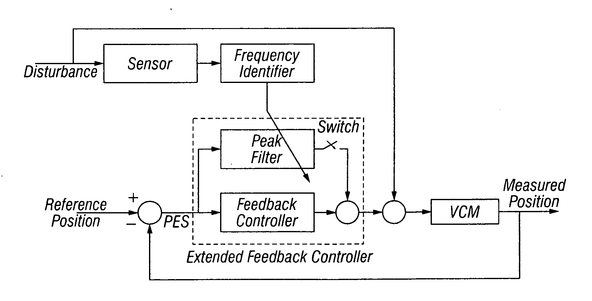
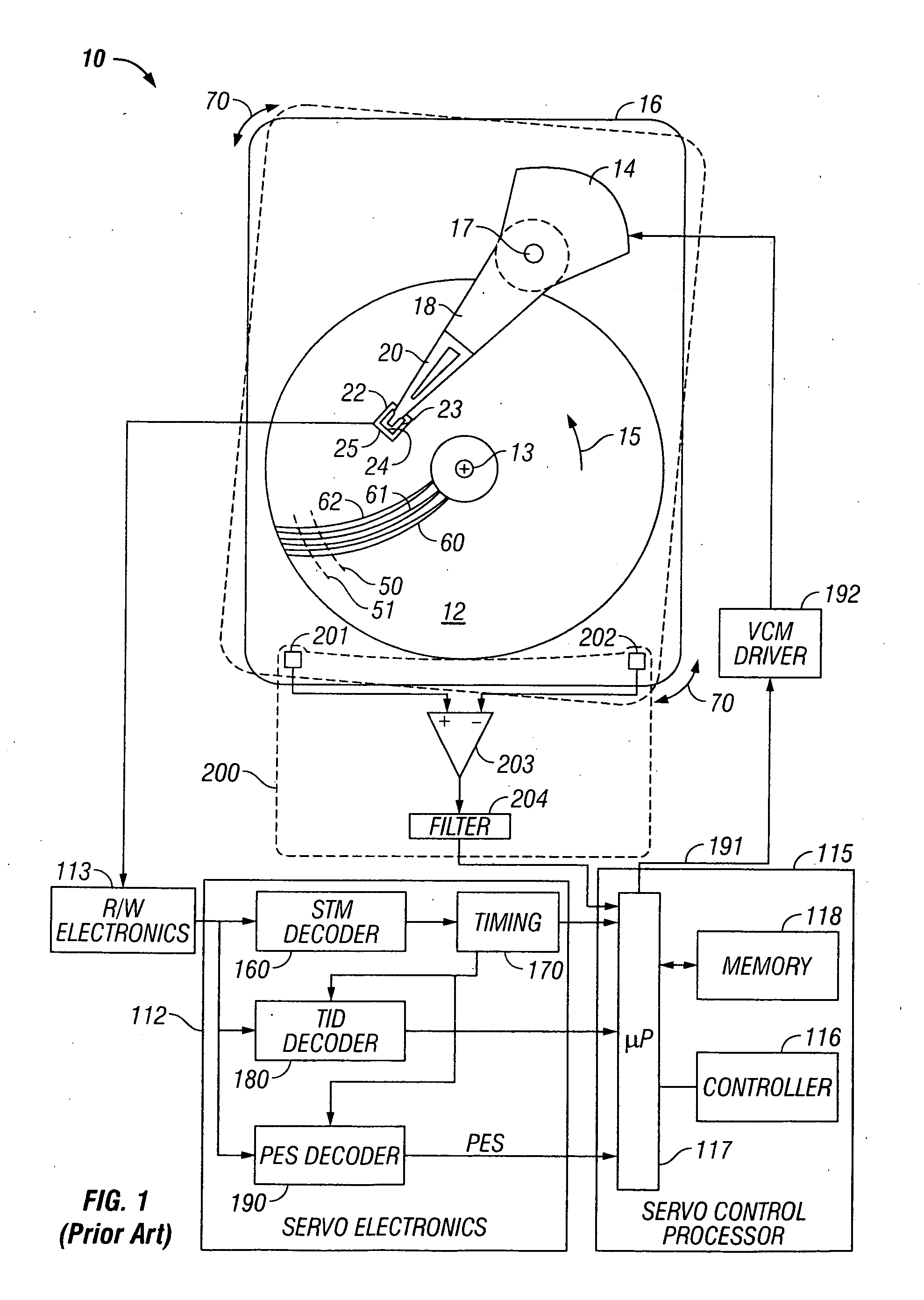
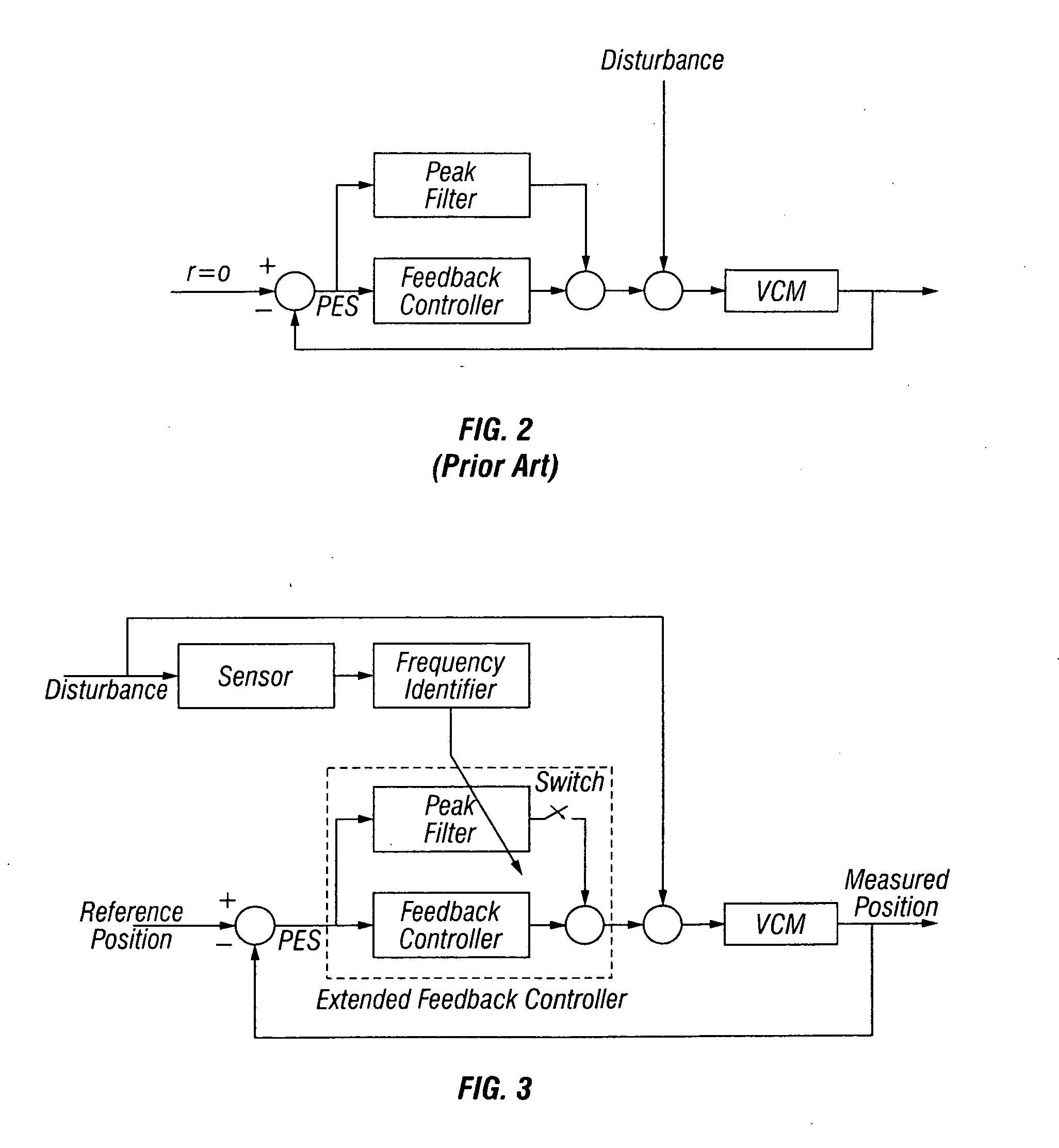
[0019]FIG. 1 is a block diagram of a prior art magnetic recording HDD 10 having a disturbance sensor 200. The disturbance sensor 200 is shown as a rotational vibration (RV) sensor for detecting rotational vibrations substantially in the plane of the disk 12. However, for the purpose of explanation of the present invention, the HDD may use any type of sensor, such as a single-axis or multi-axis accelerometer, for detecting disturbances other than purely rotational vibrations. In prior art HDDs with disturbance sensors, like the HDD shown in FIG. 1, the disturbance sensor may be used in a feedforward controller to provide a control signal summed with the VCM actuator control signal to compensate for the disturbance.

[0020] HDD 10 includes a magnetic recording disk 12 that is rotated about an axis of rotation 13 in direction 15 by a spindle motor (not shown) mounted to the HDD housing or base 16. The disk 12 has a magnetic recording layer patterned into magnetizable blocks that define ...


PUM

PropertyMeasurementUnit
frequencyaaaaaaaaaa
cut-off frequencyaaaaaaaaaa
peak frequencyaaaaaaaaaa

Abstract

A magnetic recording disk drive has a disturbance sensor and a disturbance frequency identifier that are used to adjust the frequency of a peak filter as the disturbance frequency changes. The sensor and the frequency identifier are separate from the servo control loop and thus do not rely on the head position error signal (PES) to predict the disturbance frequency. The adjustable peak filter is coupled in parallel with the servo feedback controller. The peak filter modifies the open loop transfer function and the error rejection function of the servo control loop to provide a higher rejection at the identified frequency. The peak filter may be switched out of or uncoupled from the servo feedback controller during track-seeking or as desired, depending on the amplitude of the sensor signal or the amplitude of the PES.

Description

BACKGROUND OF THE INVENTION [0001] 1. Field of the Invention [0002] This invention relates generally to disk drives, and more particularly to a magnetic recording disk drive that includes a system for canceling the adverse effects of shock and vibration disturbances. [0003] 2. Description of the Related Art [0004] Magnetic recording hard disk drives (HDDs) use an actuator, typically a rotary voice-coil-motor (VCM) actuator, for positioning the read / write heads on the data tracks of the recording disks. The HDD has a servo control system that receives a position error signal (PES) from servo positioning information read by the heads from the data tracks and generates a VCM control signal to maintain the heads on track (track “following”) and move them to the desired track (track “seeking”) for reading and writing of data. [0005] HDDs experience disturbance forces during normal operation that affect the positioning of the heads on the data tracks. These disturbances may arise internal...

Claims


Application Information

Patent Timeline
Patent Type & Authority Applications(United States)
IPC IPC(8): G11B21/02G11B5/596
CPCG11B5/59622G11B5/5582
Inventor BAUGH, ERIC GORDONSEMBA, TETSUOWHITE, MATTHEW T.
Owner WESTERN DIGITAL TECH INC
Why Eureka
Try Eureka