Bearing unit and motor using the bearing unit

a technology of bearing unit and bearing unit, which is applied in the direction of bearings, shafts and bearings, rotary bearings, etc., can solve the problems of increasing the number of components, increasing the cost, and generating stiction, so as to simplify the assembly process and reduce the number of components. , the effect of small siz

Inactive Publication Date: 2007-08-09
SONY CORP
View PDF9 Cites 9 Cited by
  • Summary
  • Abstract
  • Description
  • Claims
  • Application Information

AI Technical Summary

Benefits of technology

[0010] Thus, there is a need for a bearing unit which can be made simple in configuration and small in size, the assembly process of which can be simplified, and in which leakage of a viscous fluid such as a lubricating oil can be prevented, and for a motor using the bearing unit.
[0013] The bearing unit and the motor using the bearing unit according to the embodiments of the present invention can be made simple in configuration and small in size, the assembly process thereof can be simplified, and the leakage of a viscous fluid such as a lubricating oil used therein can be prevented, whereby reliability thereof can be enhanced.

Problems solved by technology

In addition, where the bearing unit 200 is used for a hard disk drive (HDD), if an out-gas or mist is generated due to exudation of the lubricating oil, a trouble such as stiction may be generated.
As a result, metal-made expensive members may be needed as the housing 204 and the seal member 205, and a sealing step may be needed to apply the sealing 206 to the fastening part between the housing 204 and the seal member 205, leading to a troublesome assembling step and to increases in the number of component parts and in cost.

Method used


Image

  • Bearing unit and motor using the bearing unit
  • Bearing unit and motor using the bearing unit
  • Bearing unit and motor using the bearing unit

Examples


Embodiment Construction

[0028] Now, some embodiments of a bearing unit and a motor using the bearing unit to which the present invention is applied will be described below referring to the drawings.

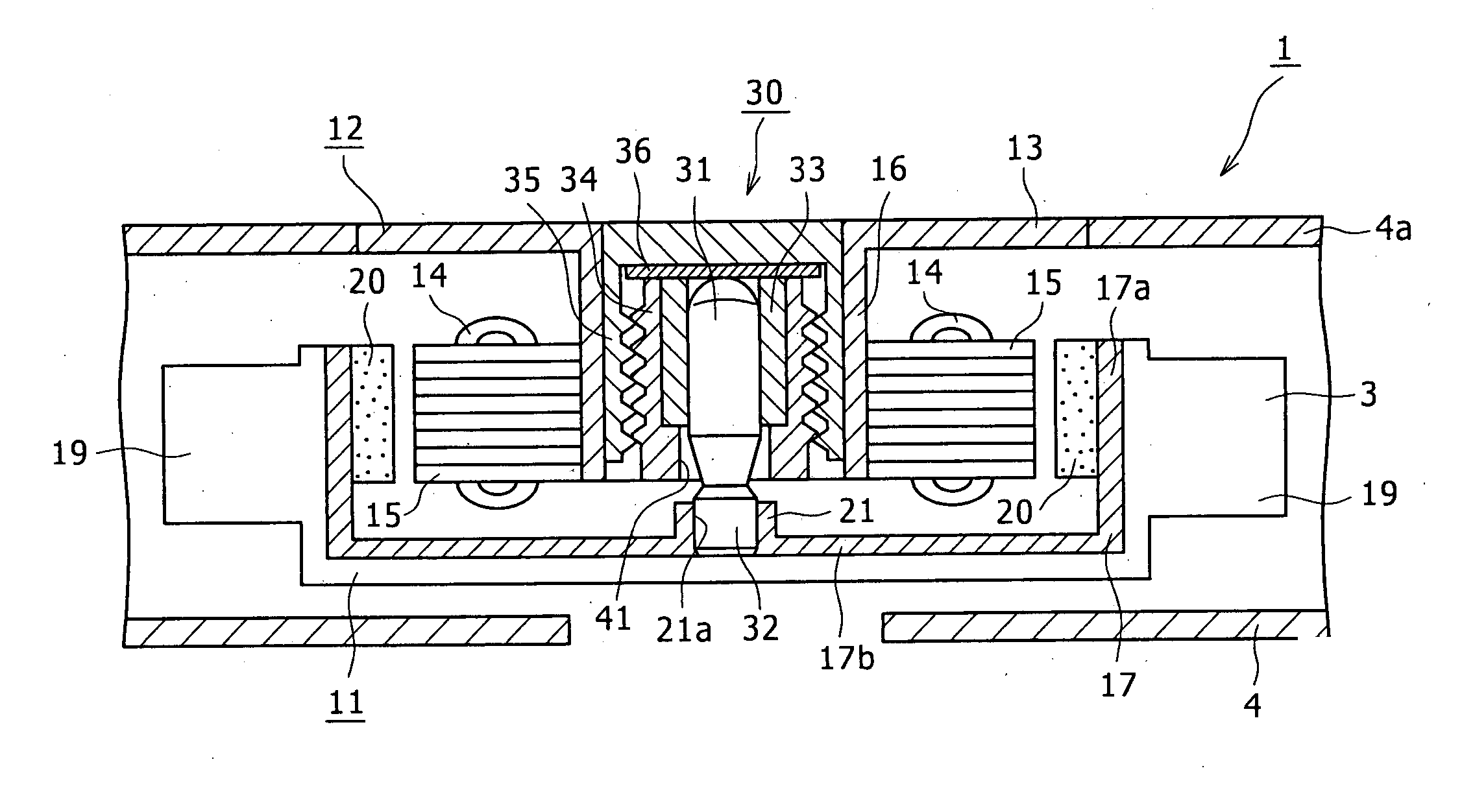
[0029] Here, a motor for use in a radiator of an electronic apparatus such as a portable type computer, which is an information processing apparatus for applying arithmetic operations or the like to various information, will be described. The radiator is provided in the inside of the portable type computer or the like. The radiator includes a metallic base, a motor 1 mounted onto the base, a fan 3 rotated by the motor 1, a fan case 4 encasing the fan 3, and a heat sink. The motor 1 for driving the fan 3 of the radiator to rotate will be described in detail below.

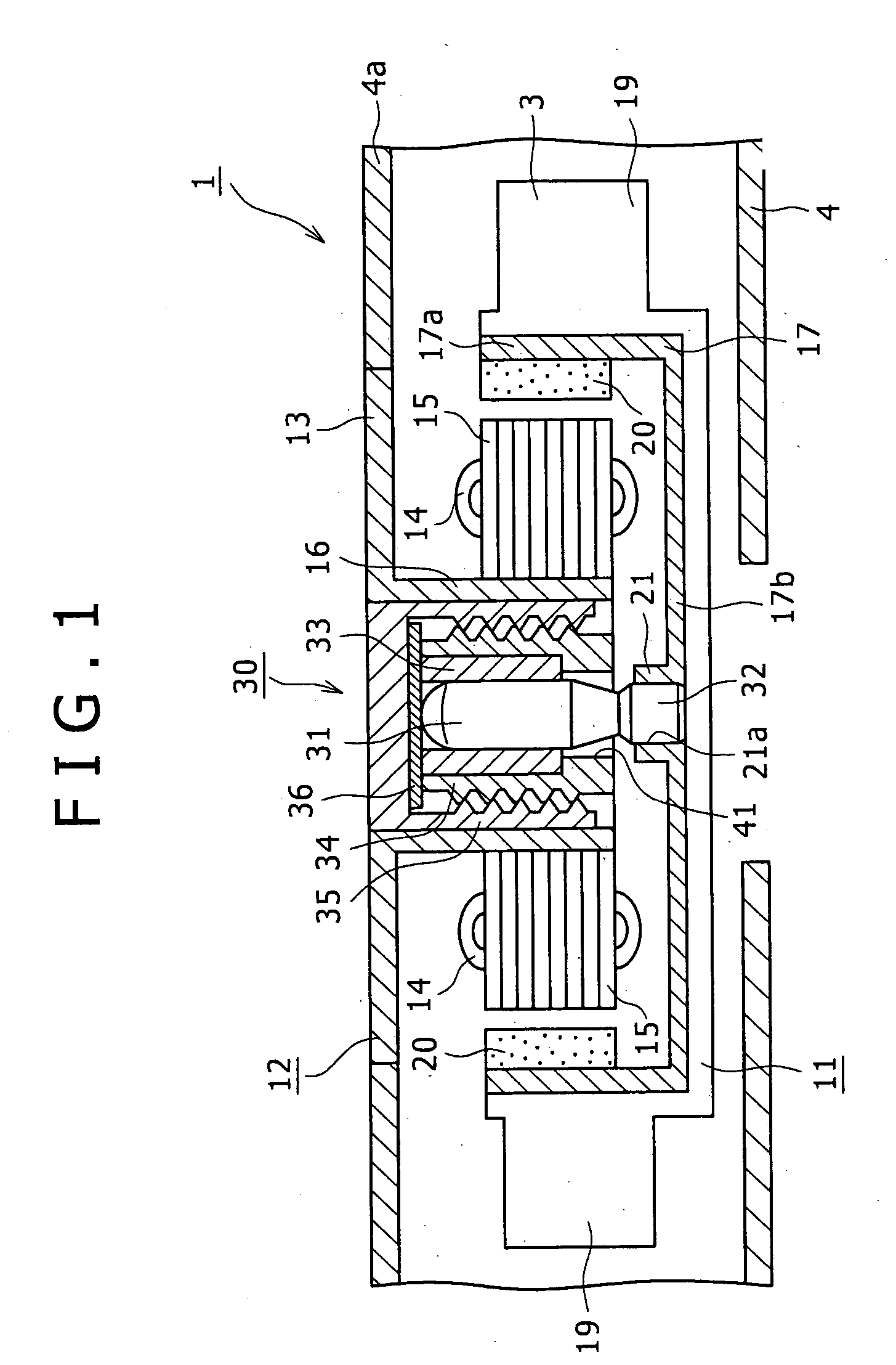
[0030] The motor 1 using a bearing unit 30 according to an embodiment of the present invention includes a rotor 11 and a stator 12, as shown in FIG. 1.

[0031] The stator 12 is provided integrally on a top plate 4a side of the fan case 4 encasing the fa...


PUM


Abstract

A bearing unit includes: a radial bearing for bearing a shaft in the circumferential direction of the shaft; a first housing member provided on the outer periphery side and on one end side in the axial direction of the radial bearing and operative to hold the radial bearing; and a second housing member provided on the outer periphery side of the first housing member and on the other end side in the axial direction of the radial bearing, wherein the first and second housing members are united by a screw part provided on the outer periphery side of the first housing member and a screw part provided on the inner periphery side of the second housing, so as to sealingly contain the radial bearing, with a shaft passage hole provided on one end side or the other end side in the axial direction so as to permit the shaft to pass therethrough; and the inside of the united first and second housing members is filled with a viscous fluid.

Description

CROSS REFERENCES TO RELATED APPLICATIONS [0001] The present invention contains subject matter related to Japanese Patent Application JP 2006-031505, filed in the Japanese Patent Office on Feb. 8, 2006, the entire contents of which being incorporated herein by reference. BACKGROUND OF THE INVENTION [0002] 1. Field of the Invention [0003] The present invention relates to a bearing unit bearing a rotating shaft rotatably or bearing a rotating body rotatably relative to a shaft, and a motor using the bearing unit. [0004] 2. Description of the Related Art [0005] As a bearing unit for bearing a rotating body rotatably, there has been known a unit configured as shown in FIG. 14. [0006] The bearing unit 200 shown in FIG. 14 supports a rotating shaft 201 rotatably, and includes radial bearing means 202 such as a slide bearing for bearing the rotating shaft 201 in the circumferential direction of the rotating shaft 201, thrust bearing means 203 such as a pivot bearing formed of a polymeric ma...

Claims


Application Information

Patent Timeline
Patent Type & Authority Applications(United States)
IPC IPC(8): F16C32/06
CPCF16C33/107F16C17/107
Inventor SHISHIDO, YUJI
Owner SONY CORP
Why Eureka
Try Eureka