Cable bolt

Inactive Publication Date: 2007-08-09
GARFORD PTY LTD
View PDF8 Cites 11 Cited by
  • Summary
  • Abstract
  • Description
  • Claims
  • Application Information

AI Technical Summary

Benefits of technology

[0007] In accordance with a first aspect of the present invention there is provided an improved cable bolt comprising a tendon composed of a plurality of strands, the tendon having a plurality of bulbous portions, wherein all the strands in each bulbous portion are spaced apart from one another

Problems solved by technology

When multi-strand cable bolts provided with bulbs or expanded portions are used to stabilize a rock surface of a coal mine, as described above, the bulbs or expanded portions tend to collapse under the load placed on the cable bolt when the tendon is tensioned to stabilize the

Method used


Image

  • Cable bolt
  • Cable bolt
  • Cable bolt

Examples


Embodiment Construction

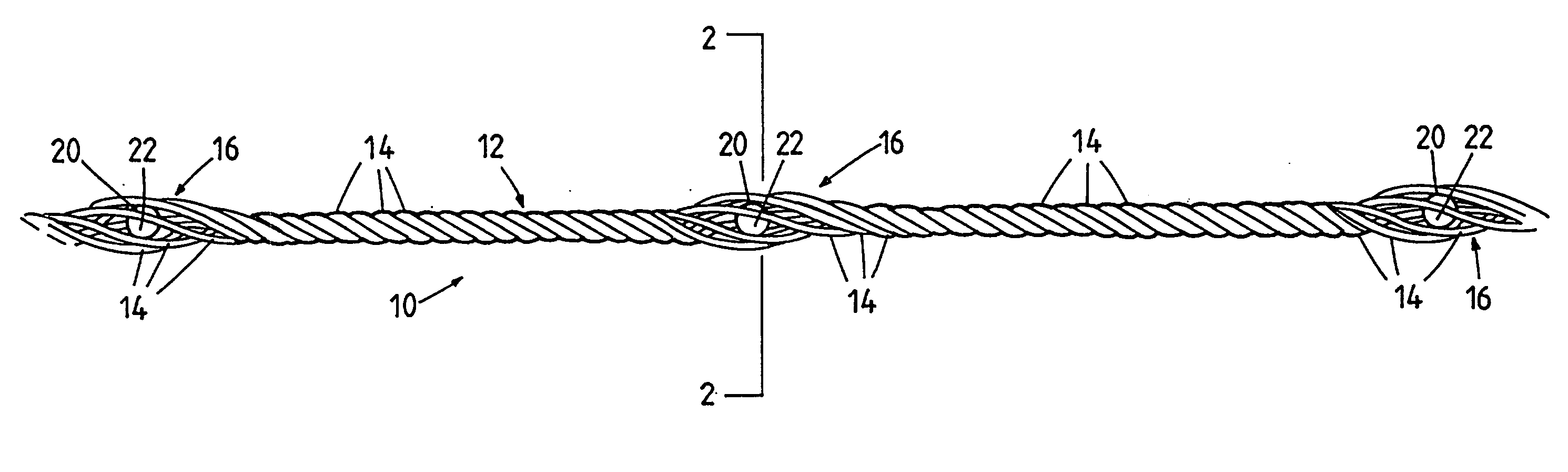
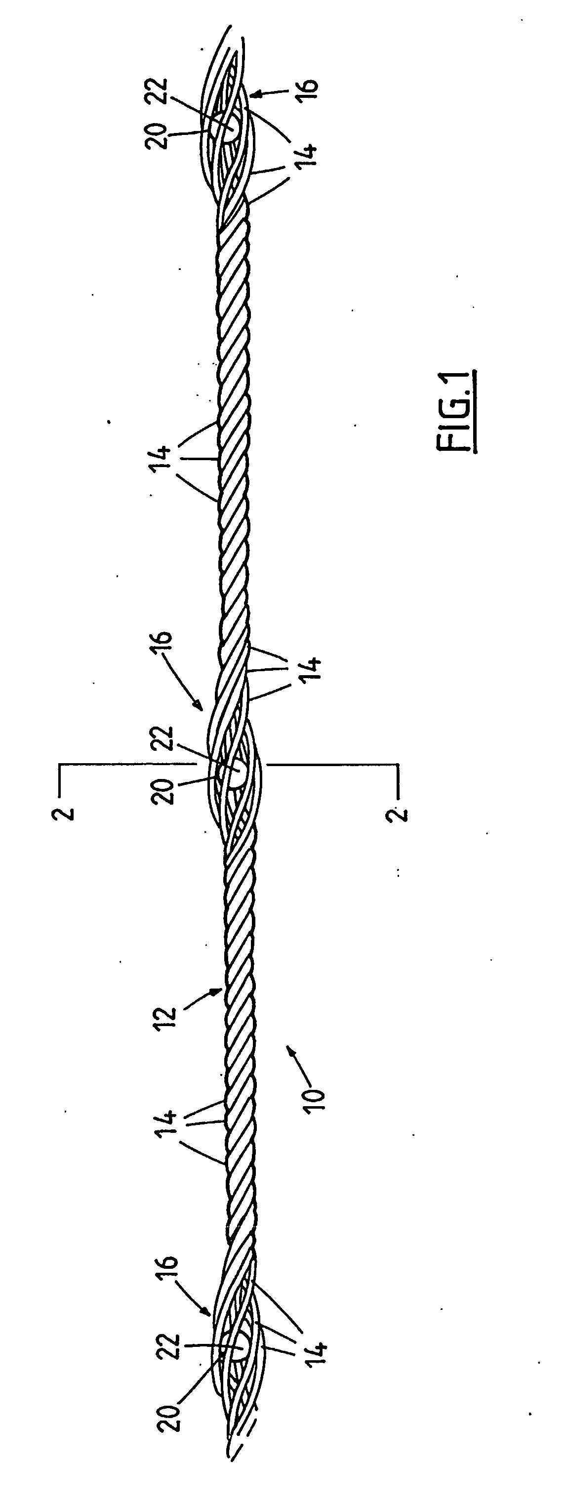
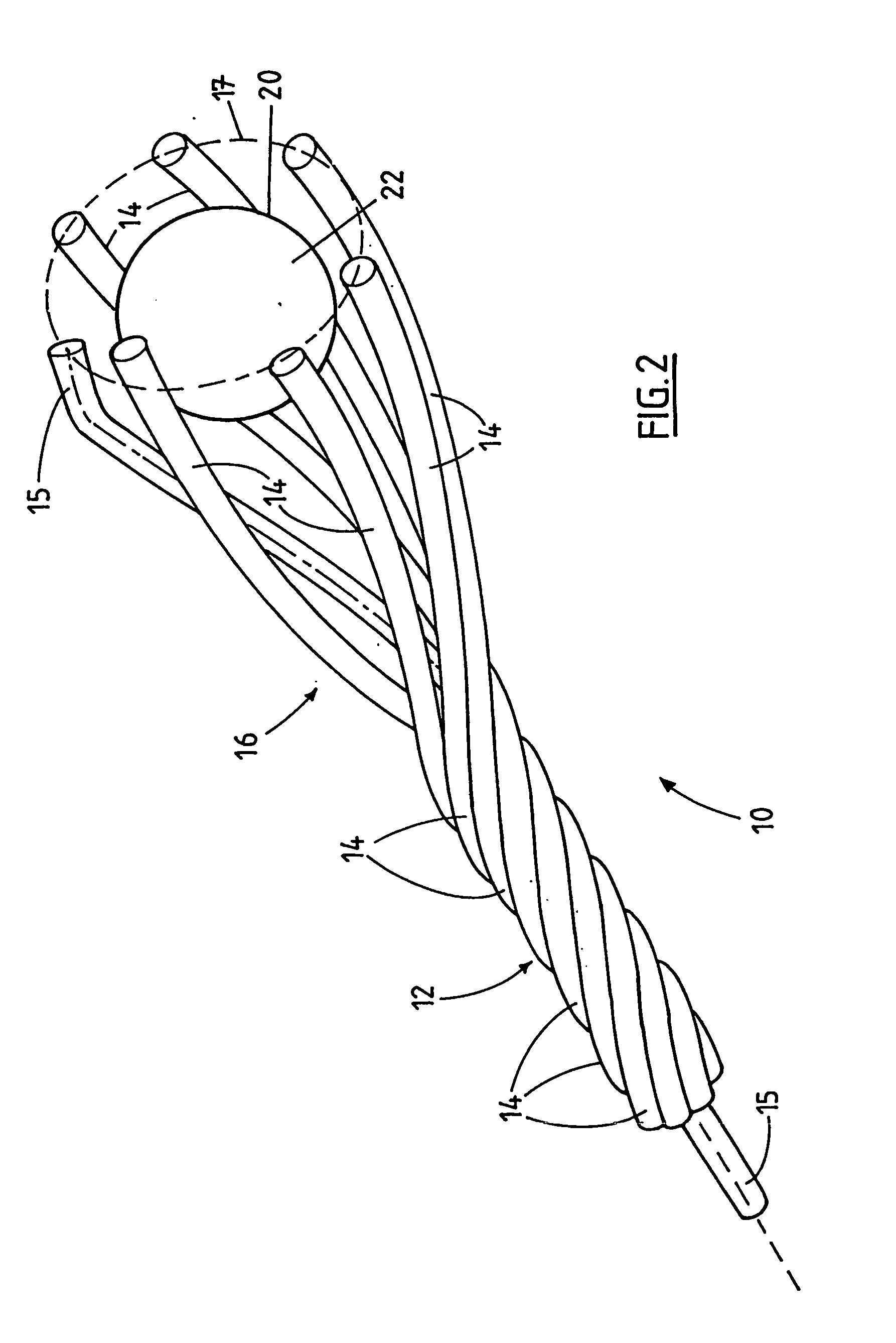
[0011] Referring to the Figures, wherein like numerals and symbols refer to like parts throughout, there is shown a cable bolt 10 comprising a steel tendon 12. The tendon 12 is composed of a plurality of outer strands 14 helically wound around a centre strand 15 to form the tendon 12. As shown, there are six outer strands 14 wound around the centre strand 15. The tendon 12 has a plurality of bulbous portions 16 spaced apart from one another along the length of the tendon 12.

[0012] The portions of the strands 14 and 15, in the bulbous portions 16, are spaced apart from each other around the circumference of the bulbous portions 16, as shown. The section line 2-2 has been taken through the broadest part of the bulbous portion 16. As seen in FIG. 2, the centre strand 15 is displaced away from the centre of the tendon 12. Typically, the bulbous portion 16 has a bulb diameter substantially as large as the diameter of the smallest tube through which the cable bolt 10 will pass.

[0013] Th...


PUM


Abstract

A cable bolt is provided that is suited to stabilize rock surfaces, particularly to withstand loads placed on the cable bolt when tensioned to stabilize rock surfaces of coal mines. The cable bolt comprises a tendon composed of a plurality of strands, the tendon having a plurality of pre-formed bulbous portions. The bulbous portions house rigid elements, such as a ball bearing, which are inserted after the bulbous portions are formed. When the cable bolt is tensioned or stressed, the load placed on the bulbous portion will be resisted by the rigid element housed within the bulbous portion, thereby preventing the bulbous portion from collapsing.

Description

FIELD OF THE INVENTION [0001] The present invention relates to an improved cable bolt, in particular to an improved cable bolt adapted for use in coal mining. BACKGROUND OF THE INVENTION [0002] Cable bolts are steel tendons inserted into bore holes in a rock surface to stabilize the rock surface against collapse. In hardrock mining, the whole length of the tendon is grouted, and a plate is attached to the tendon adjacent to the rock surface. The tendon is then stressed; the plate bears upon the rock surface and thereby stabilizes the rock surface. [0003] Tendons typically comprise a plurality of steel strands wound together to form the tendon. It is known to provide multi-stand cable bolts that are formed with bulbs or expanded portions in order to increase the surface area of the tendon in contact with the grout to more securely embed the tendon in the grout. The bulbs or expanded portions thus increase the radial confinement of the tendon within the borehole. [0004] In coal mining...

Claims


Application Information

Patent Timeline
IPC IPC(8): E21D21/00E21D20/00
CPCE21D21/0046D07B5/005E21D2021/006E21D21/006
Inventor HEDRICK, NEVILLE
Owner GARFORD PTY LTD
Why Eureka
Try Eureka