Engine casing element

a technology of engine casing and elements, applied in the direction of liquid fuel engines, machines/engines, efficient propulsion technologies, etc., can solve the problems of performance degradation, no tight sealing can be applied, and the engine efficiency is reduced, so as to achieve the effect of reducing the loss of working fluid

Inactive Publication Date: 2016-05-26
ANSALDO ENERGIA IP UK LTD
View PDF1 Cites 10 Cited by
  • Summary
  • Abstract
  • Description
  • Claims
  • Application Information

AI Technical Summary

Benefits of technology

[0003]The disclosure further provides devices and methods applicable for engine clearance control. Such clearances to be controlled may typically be found between rotating blades and stationary parts or between stationary vanes and rotating parts of turboengines. For instance the clearance present at the shrouded or non-shrouded tips of turboengine vanes or blades may be controlled such as to minimize working fluid loss over the blade or vane tips, while maintaining a minimum clearance to avoid mechanical contact between rotating and stationary engine components.

Problems solved by technology

In sections of engines where moving and stationary engine parts meet and perform relative movement, whereas a pressure differential is found across the contact area of stationary and moving engine components, a leakage flow of working fluid may result which in turn might lower the engine efficiency.
Typically, no tight sealing can be applied, due to the high relative velocity of stationary and moving parts and moreover by virtue of the potentially high temperatures inherent in the process.
As various components of the engine will have different thermal expansion and will moreover expand—or contract—with different time behavior upon a change of the operation parameters, the clearance needs to be adapted to worst case conditions, whereas the clearance in other operational states then exceeds the minimum clearance required, resulting in a performance degradation.
While said performance degradation may be reduced by sealing systems the issue of clearances which vary during operation remains.
This requires, beside the mechanical complexity of such a system, a distinct hade angle of the blades to achieve the targeted clearance alteration and is not applicable for turbine blades having a small or no hade angle.
This however requires the stator to be split into segments in circumferential direction which need to be able to perform relative movement to each other, in turn resulting in additional leaking gaps having a negative impact on the overall performance of the engine.

Method used


Image

  • Engine casing element
  • Engine casing element
  • Engine casing element

Examples


Embodiment Construction

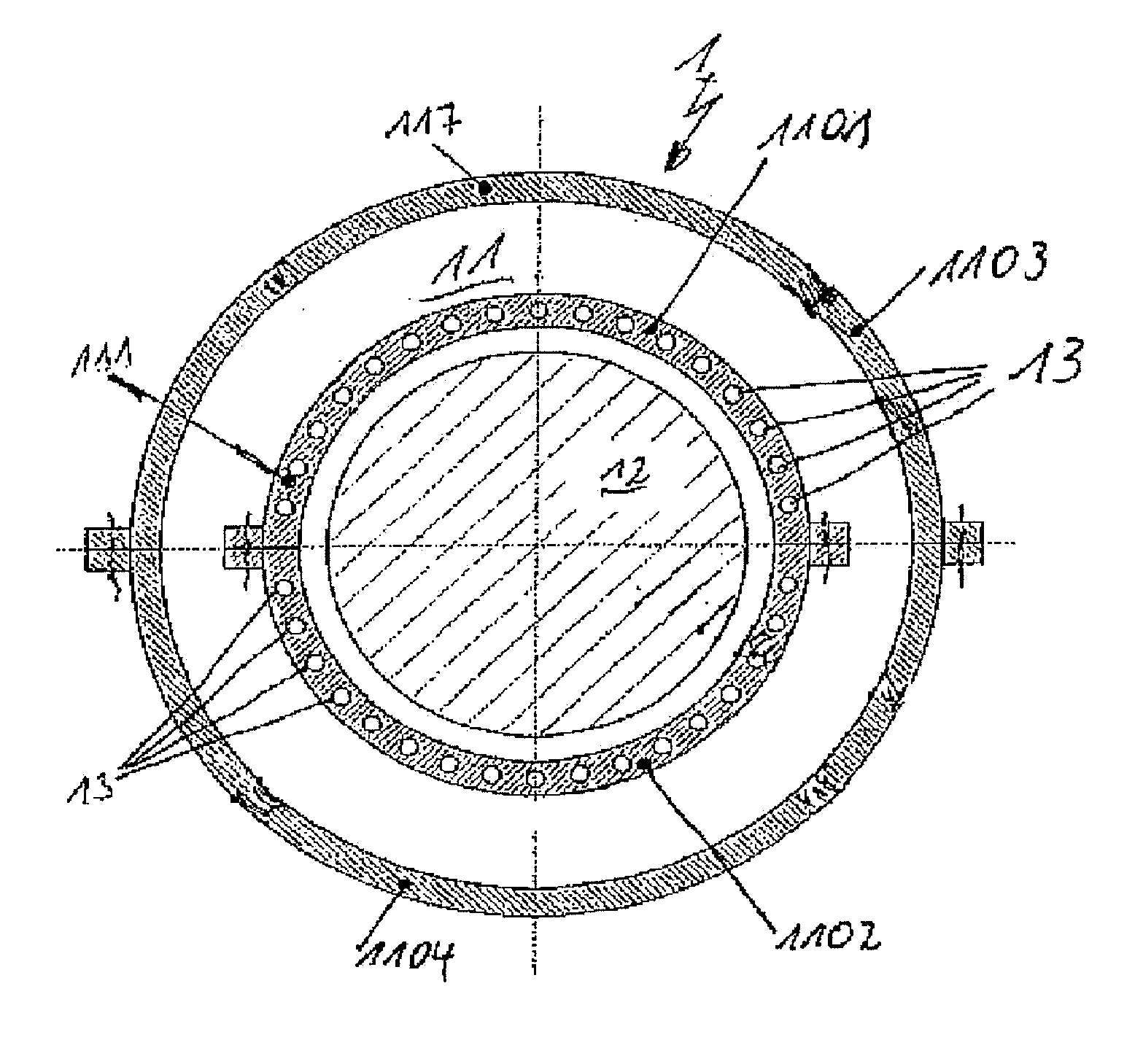
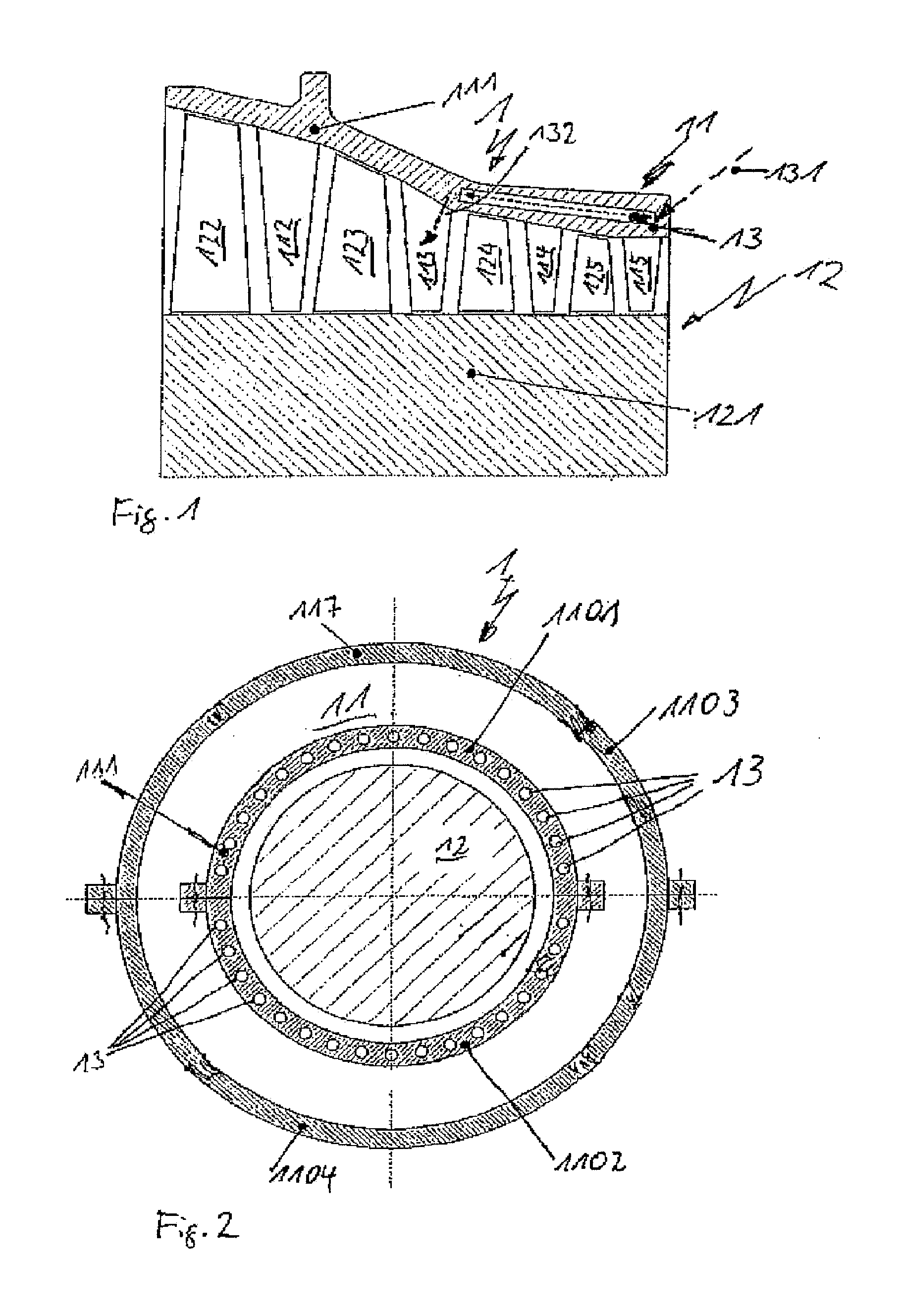
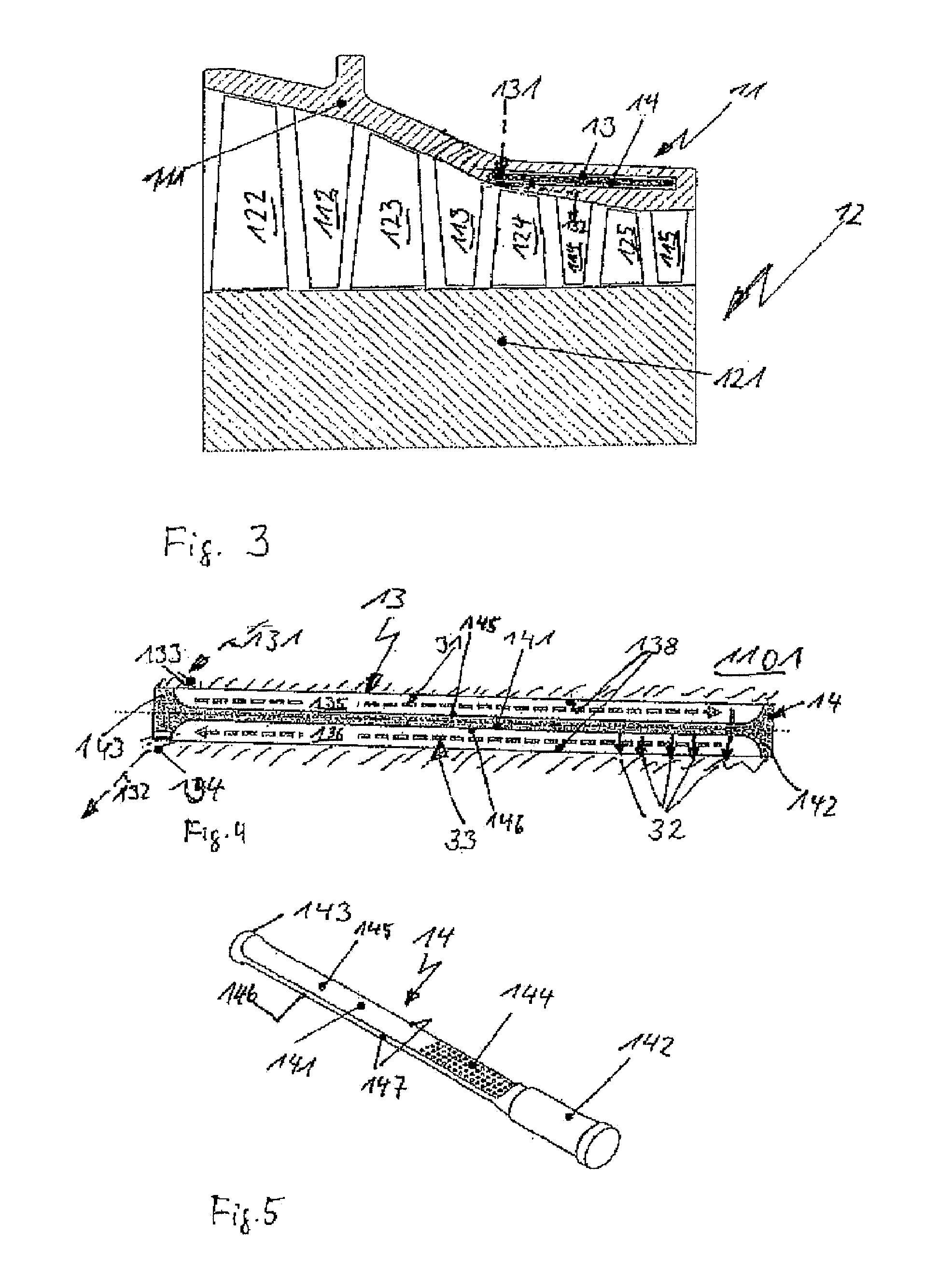
[0079]FIG. 1 depicts in a schematic representation a longitudinal section through a multistage actual expansion turbine 1. Only one half of the turbine is shown for the ease of depiction. The turbine comprises a stator 11 and the rotor 12. The stator comprises an inner housing 111, an outer housing not shown in this figure, and vanes 112, 113, 114 and 115. Inner housing 111 also serves as a vane carrier to which the turbine guide vanes are attached. The rotor 12 comprises a shaft 121 and blades 122, 123, 124 and 125. As will be appreciated by a person skilled in the art, of working fluid main flow is flowing through the turbine along the blades and vanes from right to left in this illustration. The inner housing 111 comprises the clearance control cavity 13, extending essentially in an axial direction of the turbine. The clearance control cavity 13 is arranged in the region of the first two turbine stages and covers a range where the first and second stage vanes 115 and 114 and the ...


PUM


Abstract

An engine casing element comprises at least one clearance control cavity, the clearance control cavity being delimited by a clearance control cavity inner wall and having a clearance control cavity longitudinal extent. At least one insert member is arranged inside the clearance control cavity. The insert member is arranged and configured to effect at least one of a flow guide function and a heat transfer enhancement function.

Description

TECHNICAL FIELD OF INVENTION[0001]The present disclosure related to the field of engine casing elements as described in the preamble of claim 1.[0002]In certain embodiments it relates to casing elements for turboengine casings. Such turboengines may comprise, non-limiting, turbo compressors, expansion turbines including steam turbines, turbochargers and gas turbine engines, said gas turbine engines comprising at least one turbocompressor and at least one turbine. Such gas turbine engines may for instance be provided as power generation gas turbines driving a generator, for automotive drive, for aircraft propulsion, and for other applications where mechanical drive is required. Gas turbine engines may comprise one or more turbines and / or compressors wherein typically at least one turbine and one compressor may be drivingly connected to each other, and one turbine may or may not be coupled, directly or via a gear set, to a device requiring mechanical drive. Such gas turbine engines ar...

Claims


Application Information

Patent Timeline
Patent Type & Authority Applications(United States)
IPC IPC(8): F01D17/10F01D25/08F01D9/06F01D25/24
CPCF01D17/10F01D25/24F01D25/08F01D9/06F05D2240/307F05D2220/31F05D2220/32F05D2240/125F05D2220/40F01D11/20F02C7/00F02C7/28F05D2270/44F01D11/24F05D2260/221Y02T50/60
Inventor RICHTER, JOHANNESCATALDI, GIOVANNIWIEDEMANN, NIKOLASSIMON-DELGADO, CARLOS
Owner ANSALDO ENERGIA IP UK LTD
Why Eureka
Try Eureka