Electronic ballast with PCB edge mounted output transformer/inductor

Inactive Publication Date: 2008-07-17
YANG KEVIN
View PDF1 Cites 11 Cited by
  • Summary
  • Abstract
  • Description
  • Claims
  • Application Information

AI Technical Summary

Benefits of technology

[0008]An objective of the present invention is to provide an improved output transformer assembly reconfiguration for electronics ballast. The present invention contemplates mounting a plurality of electrical components, such as variety of capacitors, transistors, diodes, and the alike on a PCB (printed circuit board) to which a detached the output transformer is connected with minimal clearance therebetween. The resulting output-transformer assembly is isolated in that it is not physically surrounded by other c

Problems solved by technology

Such conventional configuration does not provide good heat dissipation for the ballast output transformer.
Furthermore, the heat generated from the output tran

Method used


Image

  • Electronic ballast with PCB edge mounted output transformer/inductor
  • Electronic ballast with PCB edge mounted output transformer/inductor
  • Electronic ballast with PCB edge mounted output transformer/inductor

Examples


Embodiment Construction

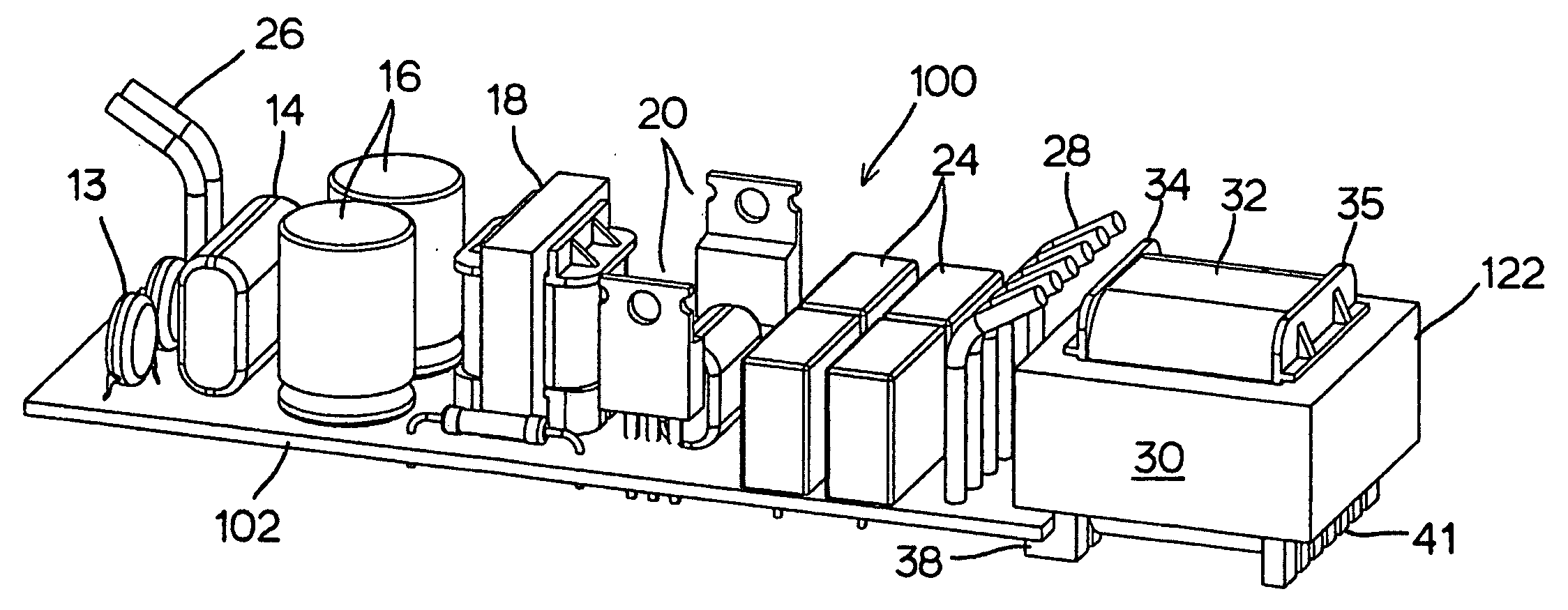
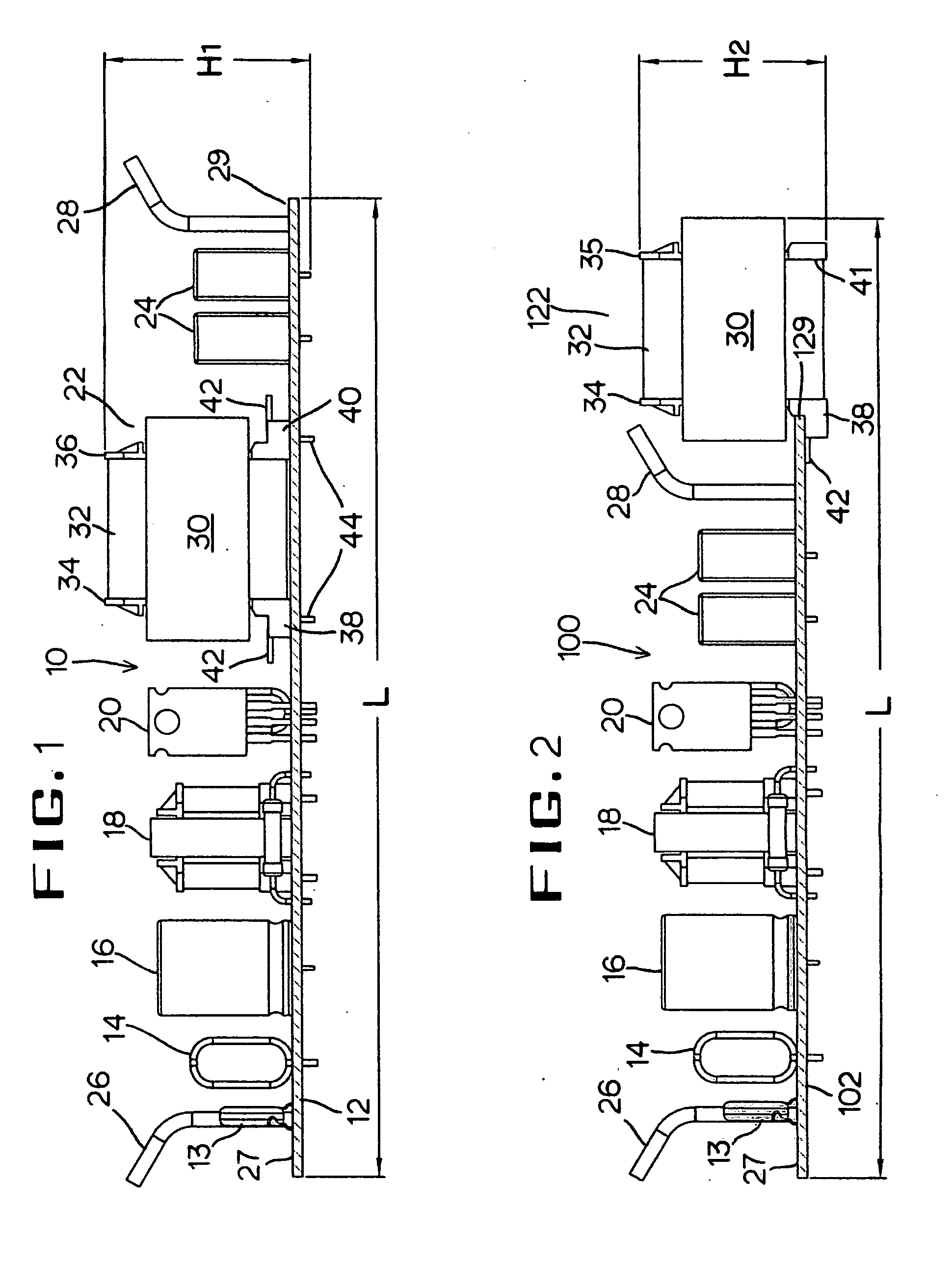
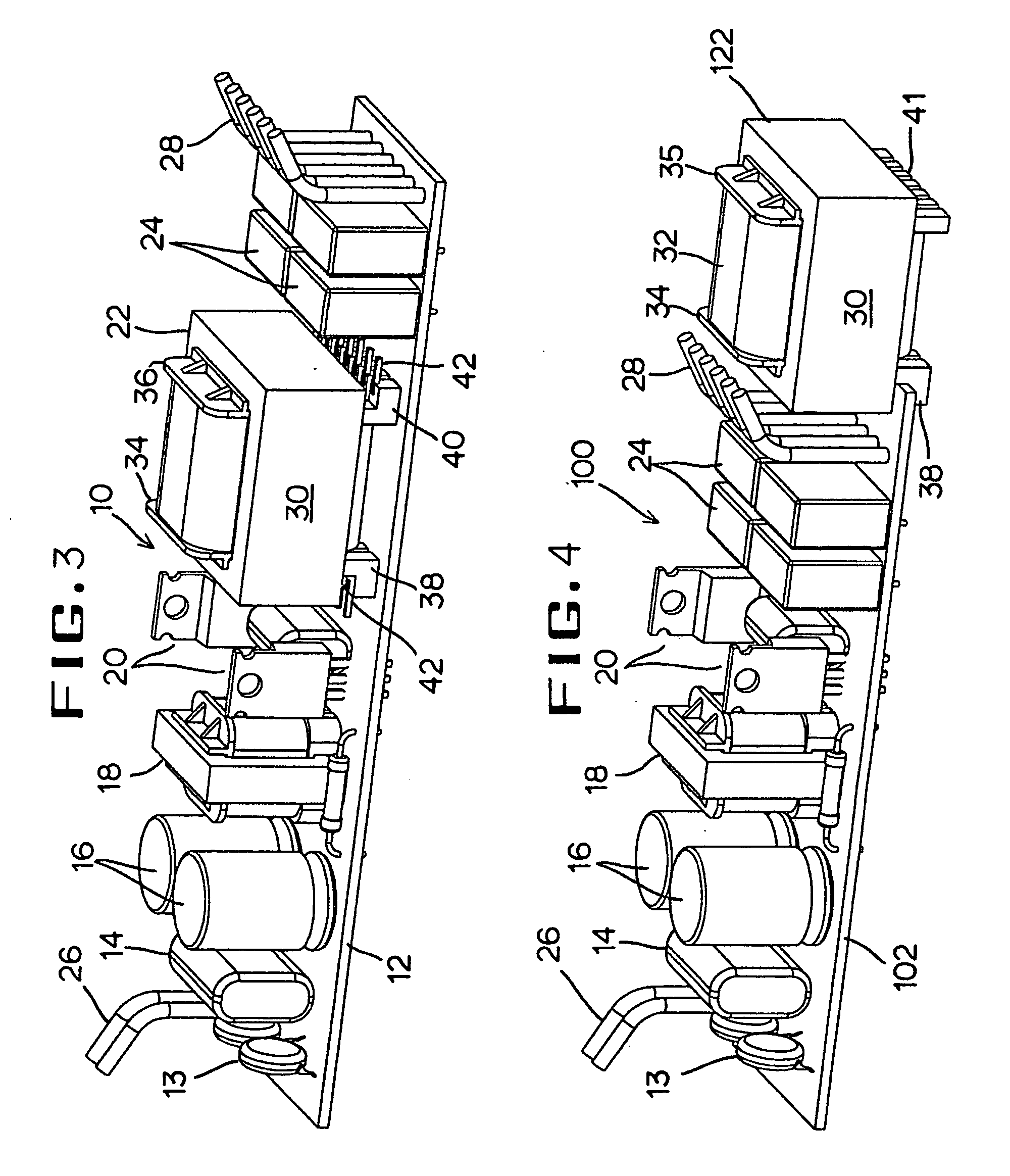
[0016]Two electronic ballasts are illustrated in the drawings as shown with their cases or enclosures removed. The old design is shown in FIG. 1, FIG. 3 and the new design is shown in FIG. 2, FIG. 4. It is well known in the art that a sheet metal enclosure consisted of an upper case and a lower case may be used to house the ballast circuitry in a dielectric sheet liner for insulation.

[0017]With reference to FIG. 1, the prior art electronic ballast PCB (printed circuit board) assembly 10 for fluorescent lamps comprises a PCB (printed circuit board) 12 having all the components mounted on the top with the thru-holes. There are some components include capacitors 13, 14, 16 and 24, an inductor 18, transistors 20, and the output transformer 22. Also inserted and soldered to the PCB (printed circuit board) are input leads wires 26 for getting the line power, and the output lead wires 28 at the opposite end 28 for supplying the high frequency current to fluorescent lamp(s).

[0018]The output...


PUM


Abstract

An output transformer or inductor for electronic ballast which having a number of electronic components including diodes, transistors, resistors, various type of capacitors and different transformers/inductors mounted on a top surface of a PCB (printed circuit board) within a compact housing which envelops the whole ballast assembly. The PCB (printed circuit board) configured to relocate the output-transformer or inductor to an edge of the PCB (printed circuit board) away from the rest of the electronic components. The output-transformer terminal (the transformer's bobbin) has at least two of L-shaped brackets locked to the PCB's (printed circuit board) edge at its top surface. The output-transformer is designed in a cantilevered mounting so that it is able to quickly dissipate its operational heat to the ballast compact case with less interfered by other components. It also saves the PCB (printed circuit board) material cost because it uses shorter PCB.

Description

BACKGROUND AND THE INVENTION[0001]1. Field of the Invention[0002]The present invention relates to fluorescent lamps electronic ballast assembly. More particularly, the present invention relates to an edgewise positioned output transformer on PCB (printed circuit board).[0003]2. Discussion of Related Art[0004]In modern life fluorescent lighting is widely used in office buildings, shopping centers, warehouses, libraries and classrooms. Due to very special operating characteristics of fluorescent lamps, each fluorescent lamp must have a ballast to make it work properly. Modern electronic ballasts comprise semiconductors, passive electronic components and transformers to convert normal power line frequencies of 50 Hz / 60 Hz to high frequencies of 20 KHz to 100 KHz for use as the lamp power source. The electronic ballasts provide illumination efficiency improvement by as much as 45 percent on actual electricity savings over conventional magnetic ballasts.[0005]Exemplary electronic ballast...

Claims


Application Information

Patent Timeline
IPC IPC(8): H05B41/02
CPCH01F38/10H01F2027/065H05K2201/10446H05K1/18H05K2201/1003H05B41/00
Inventor YANG, KEVIN
Owner YANG KEVIN
Why Eureka
Try Eureka