Guide wire assembly

Inactive Publication Date: 2007-08-09
TERUMO KK
View PDF10 Cites 37 Cited by
  • Summary
  • Abstract
  • Description
  • Claims
  • Application Information

AI Technical Summary

Benefits of technology

[0011] An object of the present invention is to provide a guide wire assembly which ensures, when inserting a guide wire into a living body, that the operator can perceive easily and assuredly the dir

Problems solved by technology

On the other hand, where a front-end section of the guide wire is straight, it may be difficult to insert the guide wire to the target site, due to straying of the guide wire depending on a branched form of the blood vessel.
However, in the case of a conventional guide wire, such as the guide wire described in Japanese Utility Model Registration No. 2601155, if the guide wire is rotated about its axis while inserting the guide wire to a target site, it becomes impossible to perceive the direction of the front-end angular section of the

Method used


Image

  • Guide wire assembly
  • Guide wire assembly
  • Guide wire assembly

Examples


first embodiment

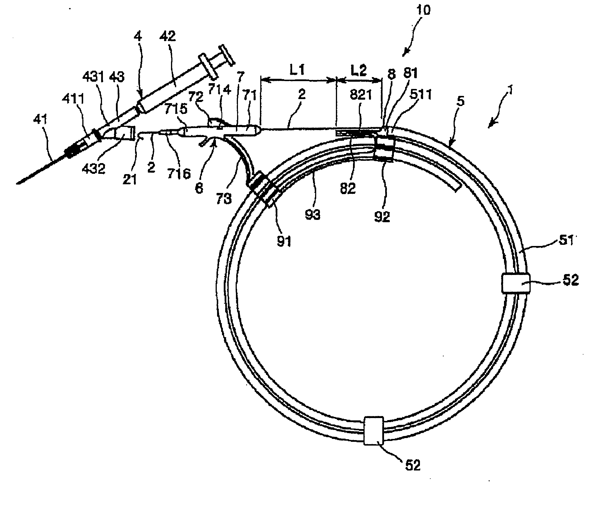
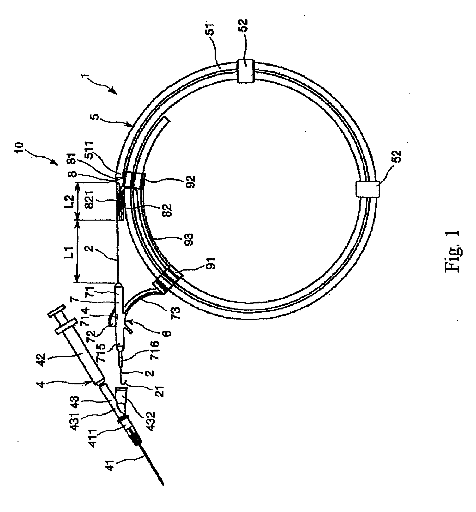
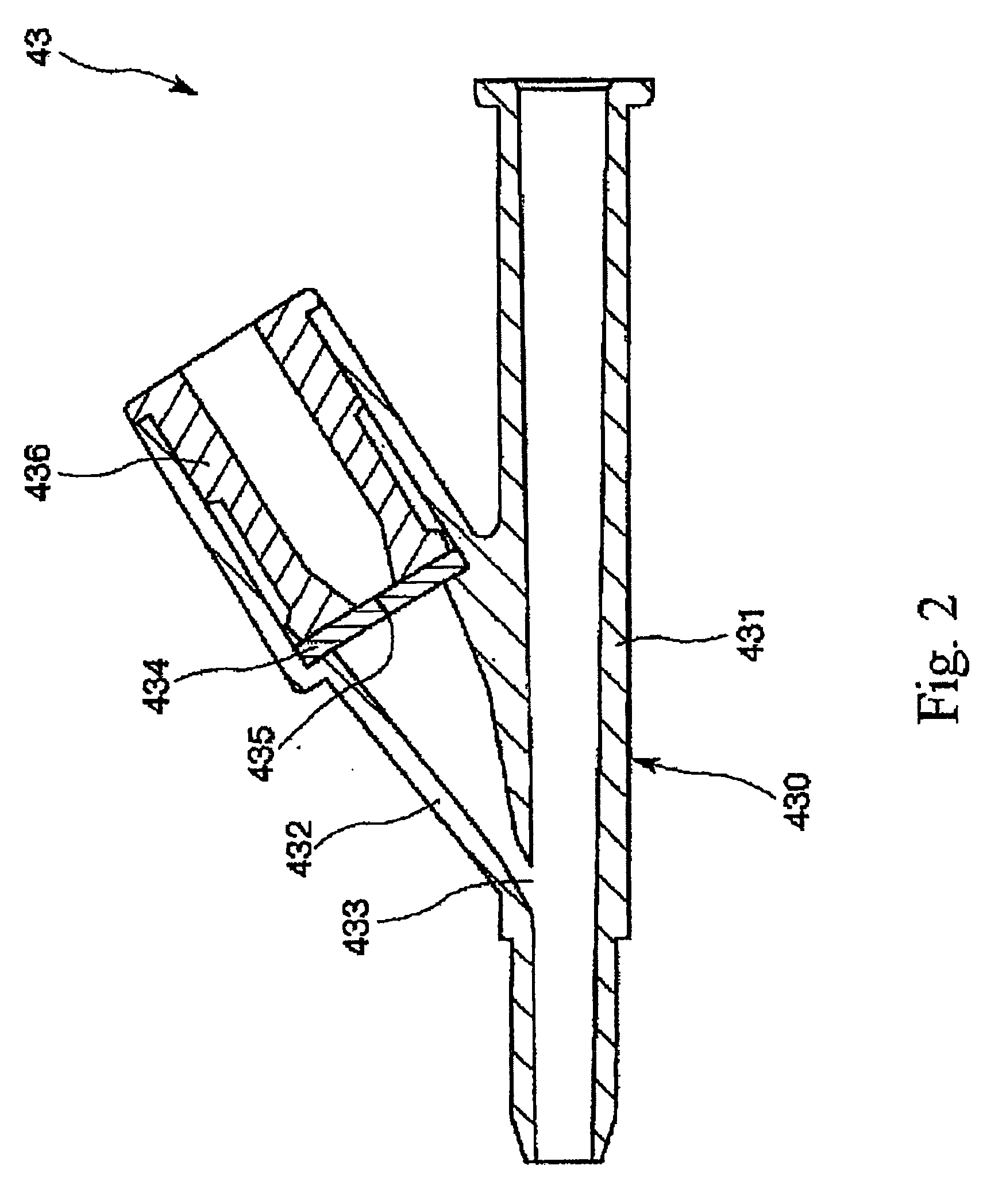
[0035]FIG. 1 is a side view showing a guide wire inserter, having a guide wire assembly according to a first embodiment of the present invention; FIG. 2 is a longitudinal sectional view showing a hub of a puncturing means illustrated in FIG. 1; FIG. 3 is a side view showing a delivering and introducing member of the guide wire assembly illustrated in FIG. 1; and FIG. 4 is a longitudinal sectional view showing the delivering and introducing member of the guide wire assembly illustrated in FIG. 1. Incidentally, for convenience in the following descriptions, the left side in FIGS. 1 to 4 shall be referred to as a “front end”, the right side as a “base end”, the upper side as an “upper” portion, and the lower side as a “lower” portion.

[0036] The guide wire inserter 10 shown in FIG. 1 is an implement (device) used for percutaneously inserting a guide wire 2 into a blood vessel in a living body, and is composed of the guide wire assembly 1 according to the present invention, together wit...

second embodiment

[0117]FIG. 9 is a cross sectional view of a pipe body of a storage section, in accordance with a second embodiment of the guide wire assembly of the present invention. The second embodiment of the guide wire assembly of the present invention shall be described below with reference to the figure, referring mainly to differences from the first embodiment, and while omitting from description items that are the same as those already addressed above.

[0118] This embodiment is the same as the first embodiment above, except that the cross sectional shape of the pipe body 51A of the storage section 5 is different.

[0119] As shown in FIG. 9, according to this embodiment, the cross sectional shape of the hollow section 514 of the pipe body 51A is non-circular. Specifically, the cross sectional shape of the hollow section 514 of the pipe body 51A is such that a part thereof (i.e., a lower part as shown in FIG. 9) in the circumferential direction of a circle is enlarged toward the outside in th...

third embodiment

[0124]FIG. 10 is a cross sectional view of a pipe body of a storage section, in accordance with a third embodiment of the guide wire assembly of the present invention. The third embodiment of the guide wire assembly of the present invention shall be described below with reference to the figure, referring mainly to differences from the first embodiment, and while omitting from description items that are the same as those already addressed above.

[0125] This embodiment is the same as the first embodiment above, except that the cross sectional shape of the pipe body 51B of the storage section 5 is different.

[0126] As shown in FIG. 10, the cross sectional shape of the hollow section 514 of the pipe body 51B in this embodiment is non-circular. Specifically, the cross sectional shape of the hollow section 514 of the pipe body 51B is an ellipse having a major axis in the vertical direction in FIG. 10, and a minor axis in the left-right direction in FIG. 10.

[0127] This configuration ensur...


PUM


Abstract

A guide wire assembly (1) includes a guide wire (2) having a main body section (22), a front-end angular section (21) and a base-end angular section (23). The guide wire assembly (1) further includes a storage section for storing the guide wire (2) inside a hollow section of a substantially annularly wound pipe body (51). The base-end angular section (23) is arranged so that it is dynamically stabilized in elasticity, in a state in which a bent direction thereof is aligned with a direction of curvature of the pipe body (51). When the base-end angular section (23) passes through the pipe body as the guide wire (2) is delivered from the storage section (5), a state is maintained in which the bent direction of the base-end angular section (23) is aligned with the direction of curvature of the pipe body (51), and the direction of the front-end angular section (21) is maintained at a predetermined direction with respect to the storage section (5).

Description

TECHNICAL FIELD [0001] The present invention relates to a guide wire assembly. BACKGROUND ART [0002] As one technique for inserting and indwelling a catheter, such as a central venous catheter, there is the Seldinger technique. The Seldinger technique is a method of inserting a catheter along a guide wire, which is set to indwell within a blood vessel. Therefore, it is very important to insert the guide wire to a target site, and to make the guide wire indwell therein, for making the catheter indwell in the target site. [0003] Insertion of a guide wire into a blood vessel is generally carried out by the following method (following steps [1] to [3])). [0004] [1] insert a cannula into the blood vessel [0005] [2] insert the guide wire into the cannula [0006] [3] push the guide wire forward so as to insert it into the blood vessel [0007] When inserting a guide wire into a blood vessel, use is made of a guide wire assembly (guide wire inserter) having a guide wire stored inside a hollow ...

Claims


Application Information

Patent Timeline
IPC IPC(8): A61M25/00A61M25/09
CPCA61M25/09041A61M25/002A61B5/15003A61B5/150236A61B5/150244A61B5/150389A61B5/150503A61B5/153A61B5/155
Inventor ASAI, TOSHIYAURAKAWA, RYUICHI
Owner TERUMO KK
Why Eureka
Try Eureka