Vehicle steering apparatus

a steering apparatus and vehicle technology, applied in the direction of steering initiation, vessel construction, instruments, etc., can solve the problems of difficult for the driver to drive the vehicle, incongruity of the driver, so as to and facilitate the driving of the vehicle

Inactive Publication Date: 2007-11-13
TOYOTA JIDOSHA KK +1
View PDF11 Cites 14 Cited by
  • Summary
  • Abstract
  • Description
  • Claims
  • Application Information

AI Technical Summary

Benefits of technology

[0013]The present invention is based upon the above-mentioned finding, and aims to provide a vehicle steering apparatus wherein a vehicle is steered with respect to an operation by a driver to a steering handle, as a motion state quantity adapted to a man's perception characteristic is correctly generated, thereby facilitating driving a vehicle.
[0015]In this case, the anticipated motion state quantity is at least either one of a lateral acceleration and a yaw rate generated on the vehicle. Further, the turning angle correcting means may correct the calculated turning angle by using the calculated steering characteristic quantity in order to decrease the phase difference between the period when the anticipated motion state quantity is generated and the period when the actual motion state quantity corresponding to the anticipated motion state quantity is generated. Moreover, the turning angle correcting means may correct the calculated turning angle by using the calculated steering characteristic quantity in order to decrease the response delay from when the turning control means starts to control the turning actuator to when the steered wheels are turned into the corrected turning angle. The steering characteristic quantity calculated by the steering characteristic quantity calculating means may be a slip angle representing a slip that is generated by the turn of the vehicle.
[0018]In the present invention having the aforesaid configuration, the operation input value to the steering handle by the driver is firstly converted into the vehicle anticipated motion state quantity (lateral acceleration, yaw rate, etc.) that relates to a turn of the vehicle, can be sensed by a driver and is in the predetermined relation of exponential function or in the predetermined relation of exponentiation function with the operation input value to the steering handle. Then, the turning angle of the steered wheels necessary for the vehicle to turn with the anticipated motion state quantity is calculated based upon the converted anticipated motion state quantity. The calculated turning angle is corrected so as to correctly generate an anticipated motion state quantity, and the steered wheels are turned into the corrected turning angle. Therefore, when the vehicle turns by the turning of the steered wheels, the anticipated motion state quantity is given to the driver as the “physical quantity of the given stimulation” in accordance with the Weber-Fechner's law. Since the anticipated motion state quantity is changed in the manner of exponential function or in the manner of exponentiation function with respect to the operation input value to the steering handle, the driver can turn the steering handle as perceiving the motion state quantity adapted to a man's perception characteristic. The driver can tactilely sense the lateral acceleration and yaw rate by the contact to each section in the vehicle. As a result, the driver can turn the steering handle as adapted to the man's perception characteristic, whereby the driver can easily drive the vehicle without having a sense of incongruity.
[0019]Since the turning angle is corrected based upon a steering characteristic quantity (e.g., a slip angle generated on the vehicle) relating to the vehicle turning state of when the vehicle actually turns, the anticipated lateral acceleration can be generated at a more correct timing. Specifically, the driver has a sense of incongruity due to the occurrence of a phase difference (phase lag or delay) between the period when the actual motion state quantity is actually generated on the vehicle and the period when the generation of the anticipated motion state quantity is anticipated. This phase difference is caused, for example, by the difference between the turning state expected beforehand and the actual turning state due to the change in the slip angle generated on the vehicle. This phase difference is considered to be a time difference until the actual vehicle turning state agrees with the turning state expected beforehand with the lapse of time. Accordingly, the actual vehicle turning state can be agreed with the turning state expected beforehand at an earlier stage by correcting the turning angle considering the slip angle or the like currently generated on the vehicle. Therefore, the vehicle can turn as reducing the time difference, i.e., phase difference, by the time when the actual motion state quantity corresponding to the anticipated motion state quantity is generated. As a result, the driver can correctly perceive the anticipated motion state quantity without having a sense of incongruity, whereby the driver can more easily drive the vehicle.
[0020]In case where, for example, the driver turns the steering handle so as to bring the vehicle into a turning state from straight running state, there may be a case where the driver has a sense of incongruity before he / she starts to perceive the anticipated motion state quantity. Specifically, the driver has to more greatly turn the steering handle, thus having a sense of incongruity, in case where a response delay (transient response delay) is great from when the steered wheels start to be turned with respect to the operation of the steering handle to when the driver starts to perceive the anticipated motion state quantity (actual motion state quantity). The case where the driver feels that the response delay (transient response delay) is great is that he / she perceives the vehicle running direction is not quickly changed to the desired direction due to the occurrence of a slip on the vehicle. Accordingly, the vehicle can be turned without the response delay by correcting the turning angle considering the slip angle or the like currently generated on the vehicle. As a result, the driver is difficult to sense the response delay (transient response delay) with respect to the operation on the steering handle, and further, the driver can perceive the correctly generated anticipated motion state quantity, whereby he / she can more easily drive the vehicle.

Problems solved by technology

The turning angle of the front wheel is not decided so as to correspond to a man's sensory characteristic by these turning methods, so that the driver has a sense of incongruity and has a hard time for driving the vehicle.
Therefore, the turning angle directly decided with respect to the steering operation by the driver is not decided so as to be adapted to the driver's perception characteristic, with the result that the driver has a sense of incongruity.
This makes it difficult for the driver to drive the vehicle.
Accordingly, in this case too, the turning angle decided with respect to the steering operation of the driver is not decided so as to be adapted to the driver's perception characteristic, and hence, this makes it difficult for the driver to drive the vehicle.

Method used


Image

  • Vehicle steering apparatus
  • Vehicle steering apparatus
  • Vehicle steering apparatus

Examples


first embodiment

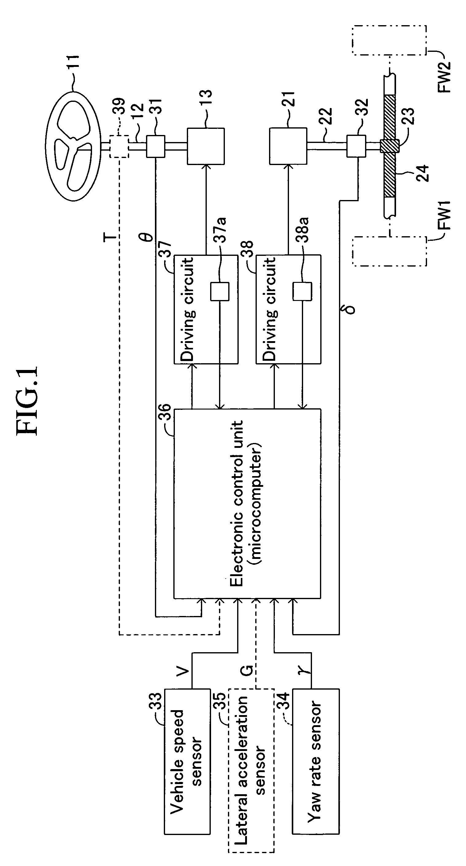
[0030]A vehicle steering apparatus according to a first embodiment of the present invention will be explained hereinafter with reference to the drawings. FIG. 1 is a block diagram schematically showing the vehicle steering apparatus according to the first embodiment.

[0031]This steering apparatus is provided with a steering handle 11 as an operating section that is turned by a driver for steering left and right front wheels FW1 and FW2, those of which are steered wheels. The steering handle 11 is fixed to the upper end of a steering input shaft 12. The lower end of the steering input shaft 12 is connected to a reaction force actuator 13 composed of an electric motor and deceleration mechanism. The reaction force actuator 13 exerts reaction force on the turning operation of the steering handle 11 by a driver.

[0032]This steering apparatus is further provided with a turning actuator 21 composed of an electric motor and a deceleration mechanism. The turning force by the turning actuator ...

second embodiment

[0076]Subsequently, a second embodiment of the present invention will be explained wherein a yaw rate is used instead of the lateral acceleration as a motion state quantity in the first embodiment. This second embodiment is also provided with a lateral acceleration sensor 35 detecting an actual lateral acceleration G which is a motion state quantity that the driver can perceive, in addition to the yaw rate sensor 34 in the first embodiment. The other configurations are same as those in the first embodiment, but the computer program executed by the electronic control unit 36 is different from the first embodiment.

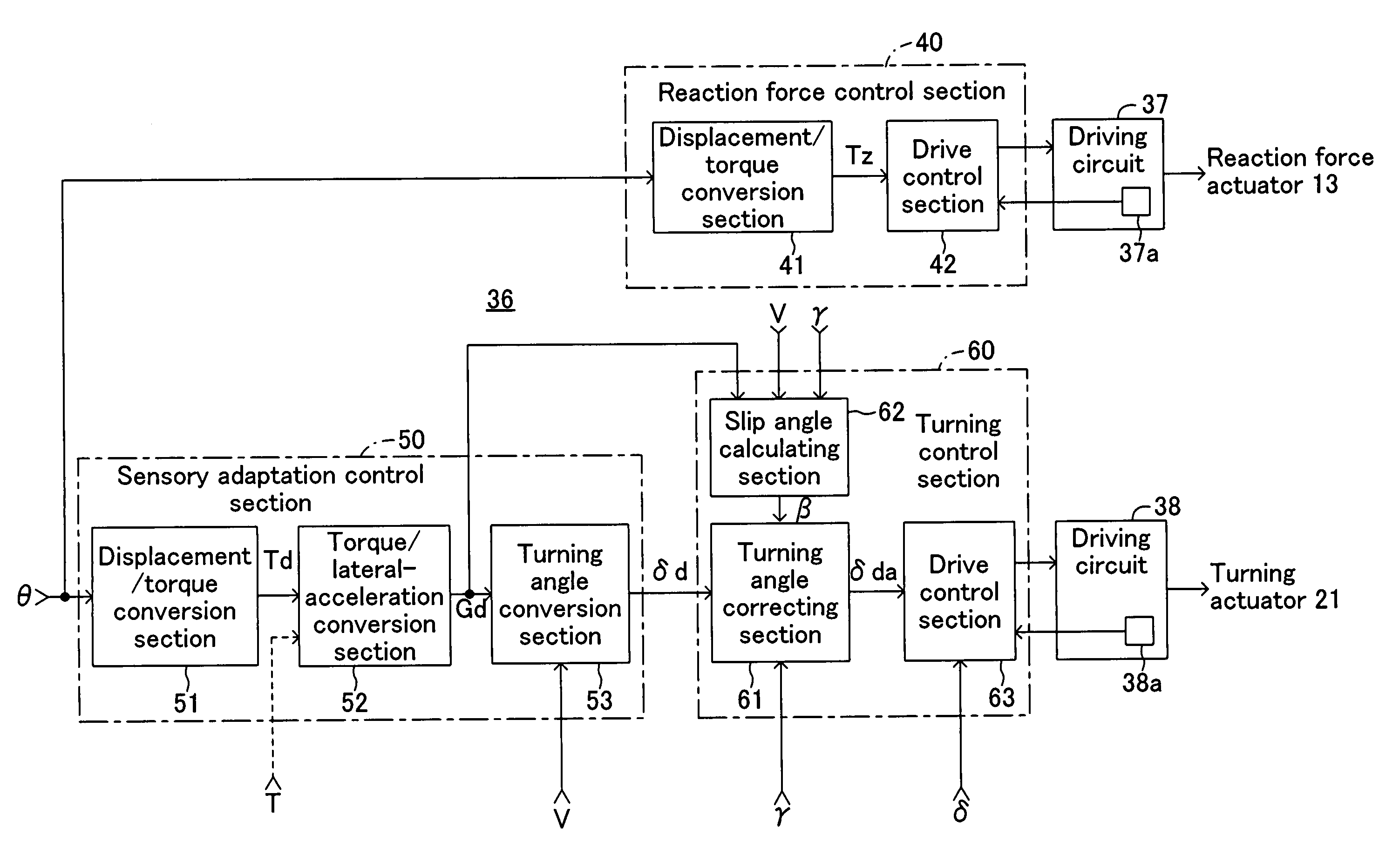
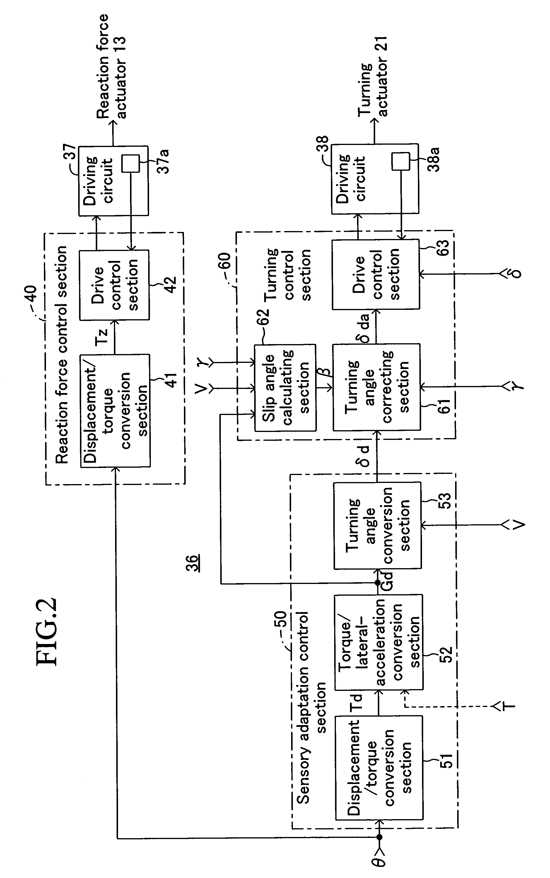
[0077]The computer program executed in the electronic control unit 36 in the second embodiment is shown in FIG. 6 by a functional block diagram. In this case, the displacement / torque conversion section 51 functions in the same manner as the first embodiment, but a torque / yaw-rate conversion section 54 is provided instead of the torque / lateral-acceleration conversion section ...


PUM


Abstract

In a vehicle steering apparatus, front wheels are controlled to be turned by a computer program processing. A displacement / torque conversion section 51 converts a steering angle θ into a steering torque Td that is in relation of exponential function. A torque / lateral-acceleration conversion section 52 converts into an anticipated lateral acceleration Gd based upon the steering torque Td. A turning angle conversion section 55 calculates target turning angles δd. A turning angle correcting section 61 obtains a slip angle β of a slip generated on a vehicle. Then, the turning angle correcting section 61 corrects the target turning angle δd based upon the obtained slip angle β, thereby calculating a corrected target turning angle δda. A drive control section 63 controls the steered wheels to be turned into the corrected target turning angle δda. According to this, a driver can correctly perceive the generated anticipated lateral acceleration Gd, whereby he / she can easily drive the vehicle.

Description

BACKGROUND OF THE INVENTION[0001]1. Field of the Invention[0002]The present invention relates to a vehicle steering apparatus of a steer-by-wire system provided with a steering handle operated by a driver for steering a vehicle, a turning actuator for turning steered wheels and a turning control device that drive-controls the turning actuator according to the operation on the steering handle for turning the steered wheels.[0003]2. Description of the Related Art[0004]The development of the steering apparatus of a steer-by-wire system of this type has recently been carried out positively. For example, the following Patent Reference 1 discloses a steering apparatus that detects a steering angle and a vehicle speed, calculates a transmission ratio that decreases with the increase in the steering angle and increases with the increase in the vehicle speed, calculates the turning angle (displacement amount of a rack shaft) of a front wheel by dividing the steering angle by this transmissio...

Claims


Application Information

Patent Timeline
Patent Type & Authority Patents(United States)
IPC IPC(8): B62D5/04B62D6/00
CPCB62D6/003B62D6/002
Inventor GOTO, TAKESHIKUROSAWA, RYUICHITOZU, KENJI
Owner TOYOTA JIDOSHA KK
Why Eureka
Try Eureka