Specification based routing of utility network systems

a utility network and specific routing technology, applied in the field of computer software, can solve the problems of project requirements often subject to change, errors in the accurate selection of the correct part by the designer, etc., and achieve the effect of greatly simplifying the process of composing a cad model of the network of the utility network

Inactive Publication Date: 2007-08-09
AUTODESK INC
View PDF5 Cites 14 Cited by
  • Summary
  • Abstract
  • Description
  • Claims
  • Application Information

AI Technical Summary

Benefits of technology

[0011] One advantage of the disclosed method is that the user specifying the routing characteristics of the utility network is not required to individually select which network elements are inserted into the CAD model. Instead, as the user specifies the routing characteristics of the utility network, a CAD application selects which network parts to insert into the CAD model, based on the routing specification. Thus, the process of composing a CAD model of a network of a utility network is greatly simplified.

Problems solved by technology

While this approach works as intended, it requires a designer to continually reference the routing specification while composing a CAD model, which may lead to errors in the designer accurately selecting the correct part.
In reality, however, project requirements are often subject to change.

Method used


Image

  • Specification based routing of utility network systems
  • Specification based routing of utility network systems
  • Specification based routing of utility network systems

Examples


Embodiment Construction

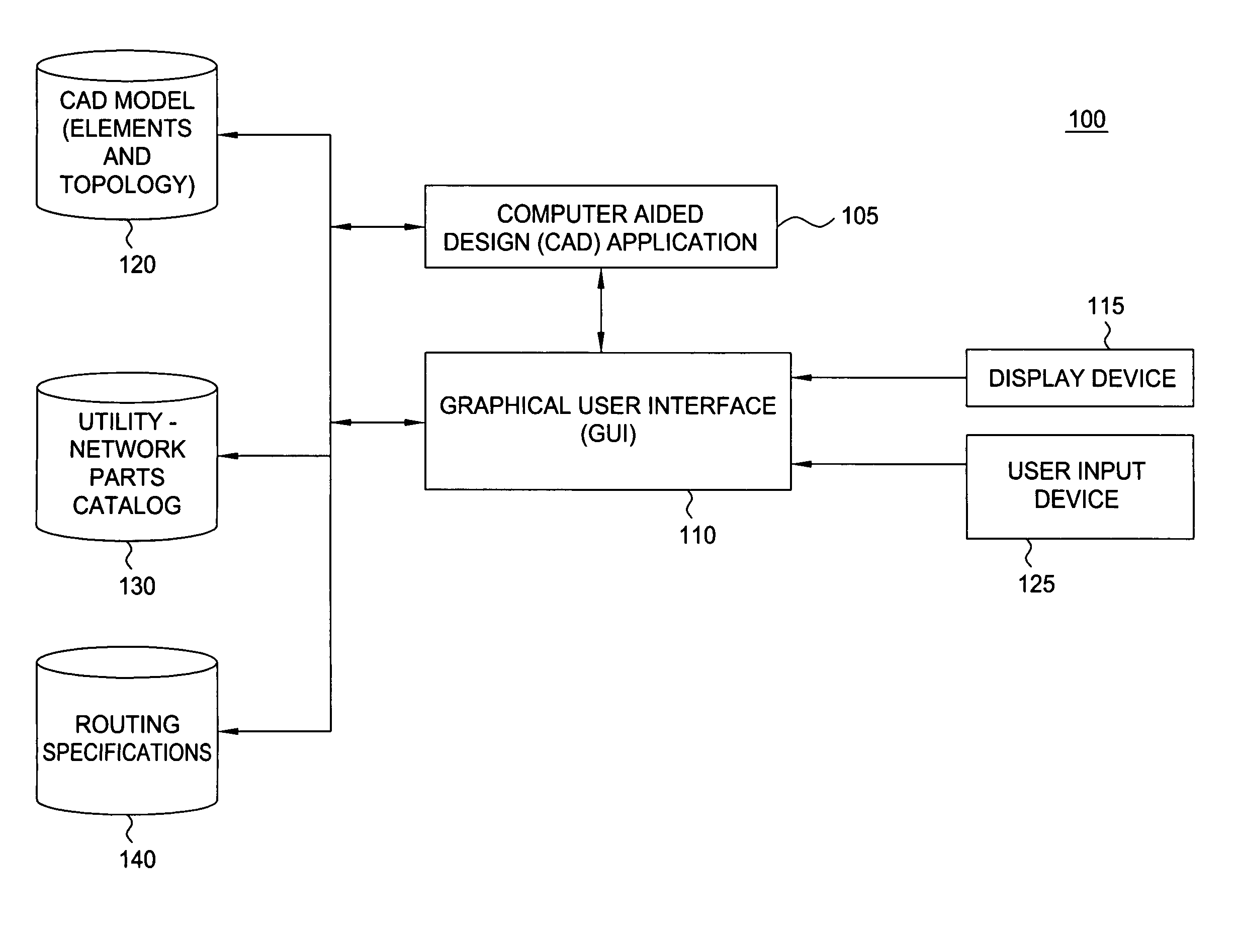
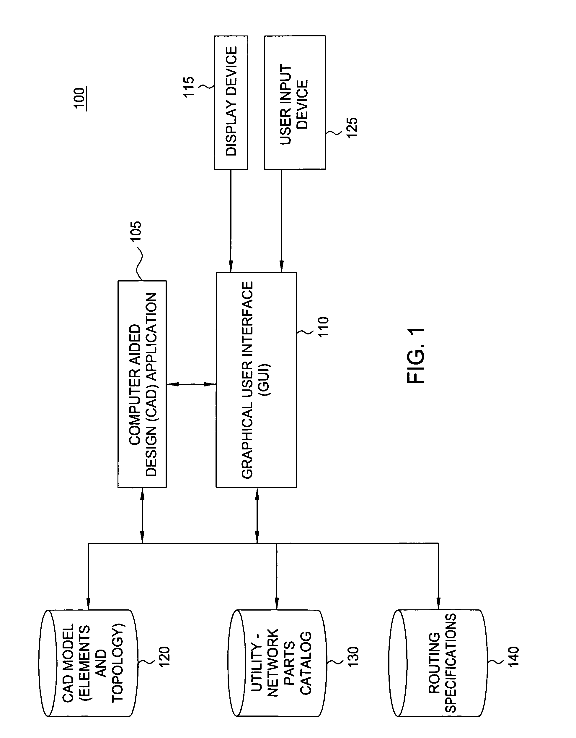
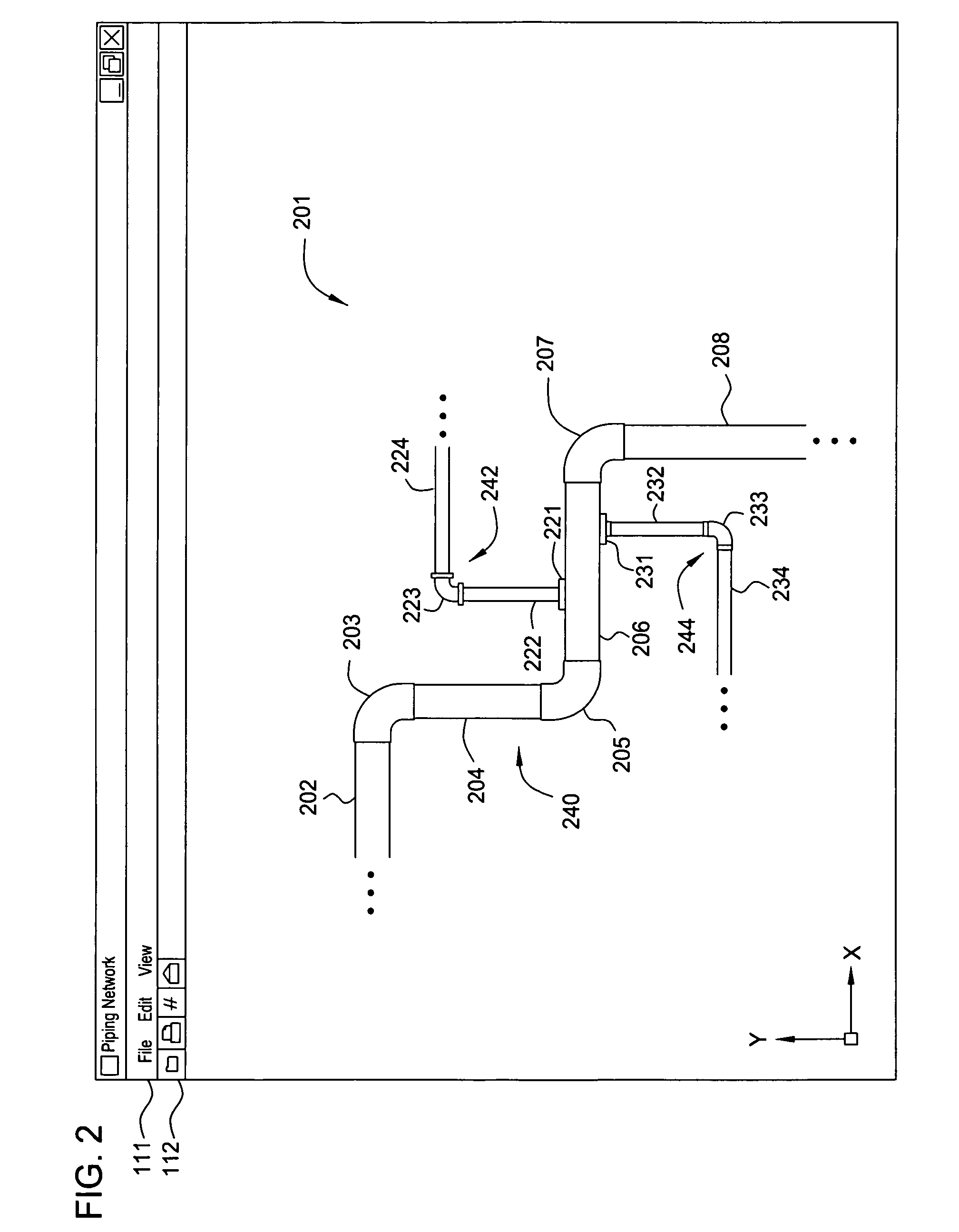
[0019] Embodiments of the invention provide a computer-aided design (CAD) environment that allows an engineer to compose a model of a utility network according to a routing specification specified for that network or design project. The routing specification allows the engineer to specify the topology of the network and the CAD application automatically places the proper utility components (e.g. pipe segments, elbows, joints, transitions, tees, etc.) in the network according to the routing specification. Typically, the routing specification identifies the proper utility components based on some aspect of the network being modeled, such as the size or diameter of pipes being routed by the designer. Alternatively, the proper utility components may depend on the material being routed, the location of the network (e.g., indoor / outdoor, above / below ground, etc), or any other criteria specified by the routing specification.

[0020] To facilitate a description of the invention, the followin...


PUM


Abstract

Embodiments of the invention allow users to compose a computer-aided design (CAD) model of a utility network. As a user specifies the routing characteristics of the utility the network (i.e., the position, length, and direction of segments of the network), a CAD application automatically selects the network parts to include in the CAD model based on a routing specification. Thus, the process of composing CAD model of a network of a utility network is greatly simplified.

Description

BACKGROUND OF THE INVENTION [0001] 1. Field of the Invention [0002] The present invention generally relates to computer software. More specifically, the present invention relates to software used to create a computer model of a utility network system. [0003] 2. Description of the Related Art [0004] The term computer-aided design (CAD) generally refers to a broad variety of computer-based tools used by architects, engineers, and other construction and design professionals. CAD applications may be used to construct computer models representing virtually any real-world construct. Commonly, CAD applications are used to generate computer models and drawings related to utility networks. For example, a CAD application may be used to compose a model of a connected system of pipes, electrical, or HVAC ductwork components. The models may be used to create a variety of two-dimensional (2D) and three-dimensional (3D) views of the utility network. Additionally, such models may be used to generat...

Claims


Application Information

Patent Timeline
Patent Type & Authority Applications(United States)
IPC IPC(8): H04L9/00
CPCG06F2217/34G06F17/509G06F30/18G06F2113/14
Inventor GHANTOUS, SAMINOREN, BO
Owner AUTODESK INC
Why Eureka
Try Eureka