

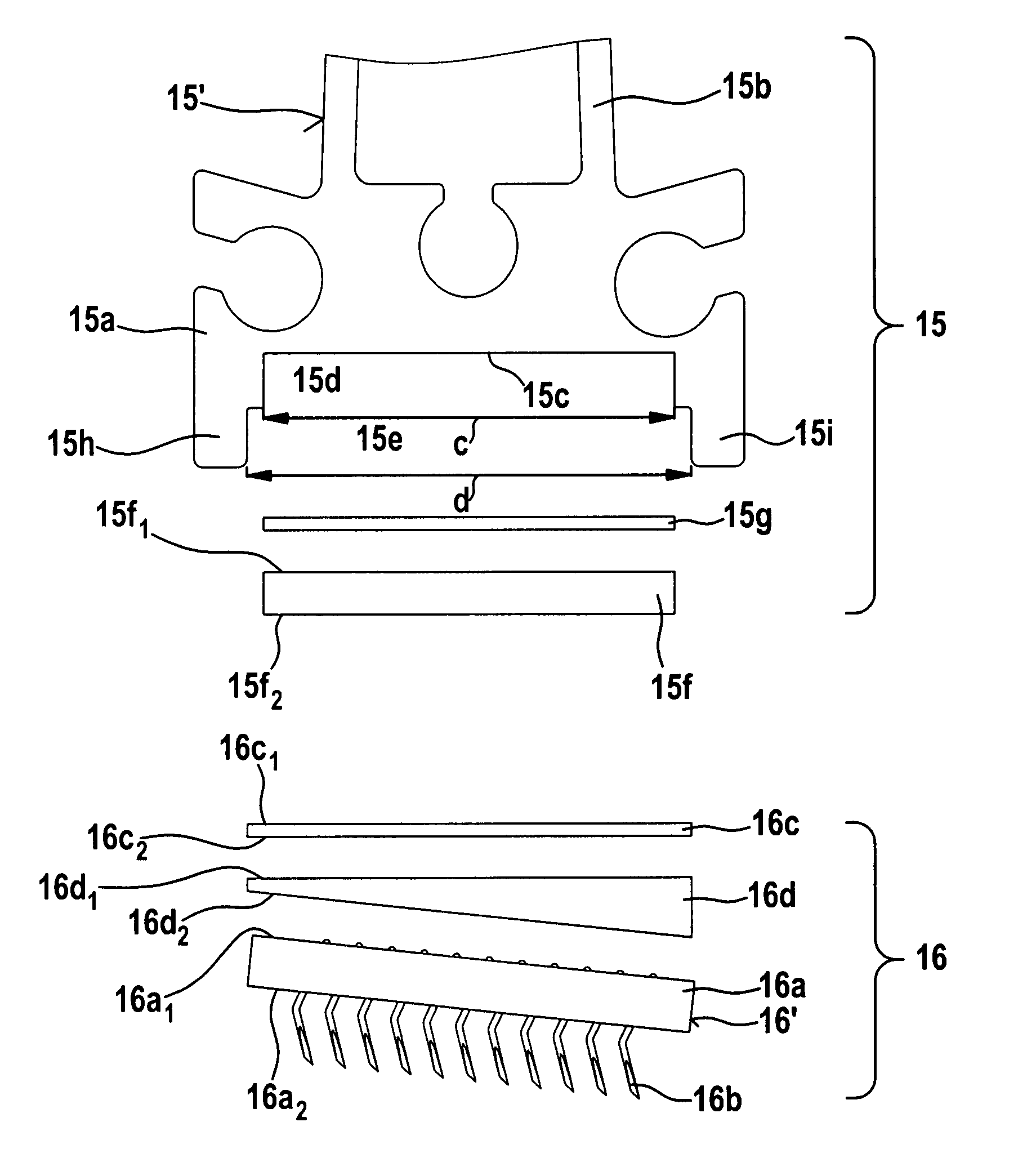
Apparatus on a carding machine for cotton, synthetic fibres and the like, in which at least one flat bar with a flat clothing is present
- Summary
- Abstract
- Description
- Claims
- Application Information
AI Technical Summary
Benefits of technology
Problems solved by technology
Method used
Image

Examples
Embodiment Construction
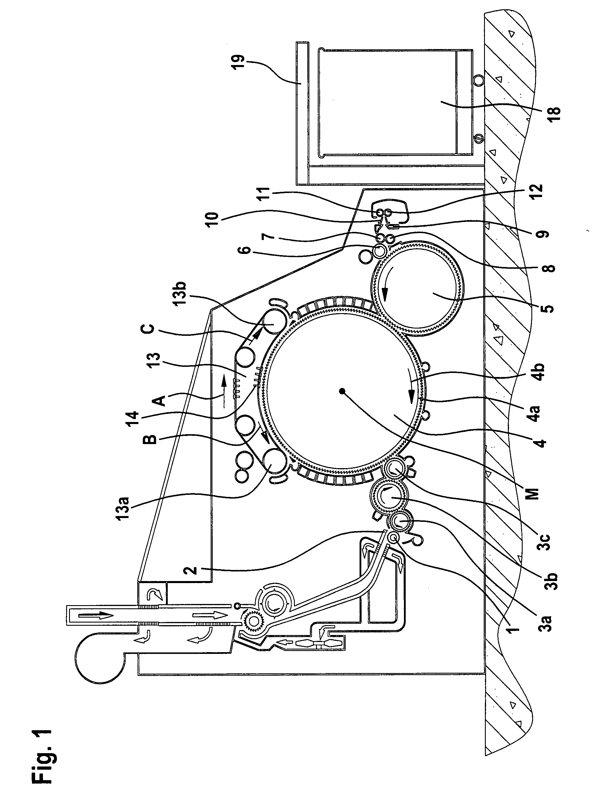
[0027]With reference to FIG. 1, a flat card, for example, a flat card known as the TC 03 (Trade Mark), made by Trutzschler GmbH & Co. KG. of Monchengladbach, Germany, has a feed roller 1, feed table 2, licker-ins 3a, 3b, 3c, cylinder 4, doffer 5, stripping roller 6, squeezing rollers 7, 8, web-guide element 9, web funnel 10, take-off rollers 11, 12, revolving flat 13 with flat guide rollers 13a, 13b and flat bars 14, can 18 and can coiler 19. The directions of rotation of the rollers are shown by respective curved arrows. The letter M denotes the midpoint (axis) of the cylinder 4. The reference numeral 4a denotes the clothing and 4b denotes the direction of rotation of the cylinder 4. The letter A denotes the working direction. Arrow B denotes the carding setting of the flat bars 14 and arrow C denotes the return transport direction of the flat bars 14.
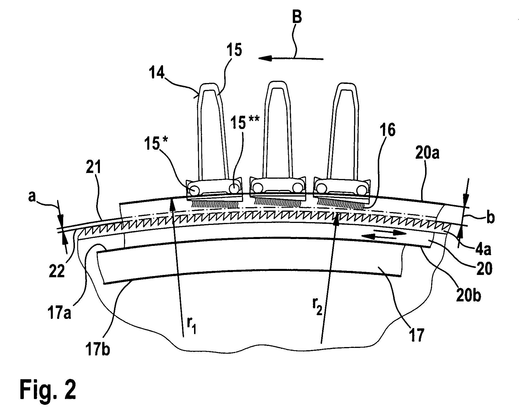
[0028]FIG. 2 shows one embodiment according to the invention. On each side of the card, a flexible bend 17 having several adjusting ...
PUM
 Abstract
Description
Claims
Application Information