
Air compressor and expander

Inactive Publication Date: 2007-08-16
HALLA CLIMATE CONTROL
View PDF7 Cites 7 Cited by
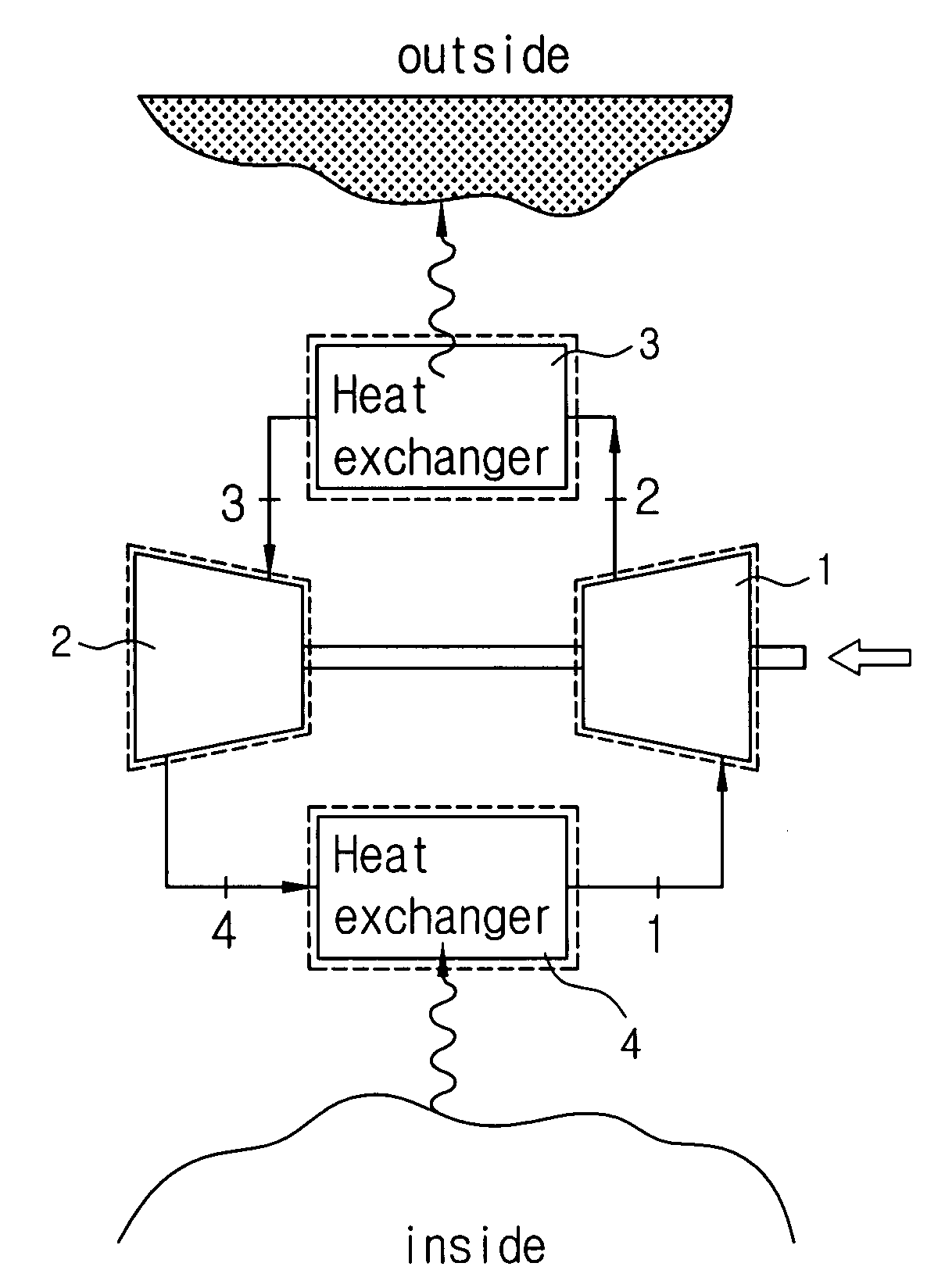
  • Summary
  • Abstract
  • Description
  • Claims
  • Application Information

AI Technical Summary

Benefits of technology

[0030]Accordingly, the present invention has been made in view of the above-mentioned problems occurring in the prior art, and it is an object of the present invention to provide an air compressor and expander that is capable of having a sufficient air flow quantity to flow therein by improving the shapes of a first rotor and a second rotor and is capable of minimizing the clearance between the first and second rotors, the clearance between the rotors and a casing, and the clearance between the rotors and end covers by improving the tooth shapes of the first and second rotors, by disposing a closing cover at both end portions of a casing for housing the first rotor and the second rotors, and by disposing a clearance-preventing means at one side of the closing cover.

Problems solved by technology

At this time, in case of an open-air cycle where cool air is supplied directly to an air conditioning space, refrigerant is respired as air itself by human beings, such that the air contaminated through mixing oil with pure air cannot be used.
If the minimal clearance is not maintained well, the efficiencies of the compressor and the expander are decreased, thereby making the system performance and efficiency undesirably deteriorated.
However, the oil injection type screw compressors can not be applied to the open-air cycle where refrigerant is respired as air itself by human beings.
Especially, while the first and second rotors 1 and 2 are rotated at a high speed, the upper and lower bearings 8 do not serve to sufficiently support the rotation, such that the interference between the protrusion 1b and the groove 2b is much generated.

Method used


Image

  • Air compressor and expander
  • Air compressor and expander
  • Air compressor and expander

Examples


first embodiment

[0049]FIGS. 5 to 8 show an air compressor and expander according to the present invention;

[0050]As shown, the air compressor and expander according to the first embodiment of the present invention includes a first rotor 10, a second rotor 20, a casing 30, first and second end covers 40 and 50, a gear part 60, and a clearance-preventing means 70.

[0051]The first rotor 10 is coupled around a driving shaft 11, and the second rotor 20 is coupled around a driven shaft 21 so as to operate in cooperation with the first rotor 10. In this case, the first rotor 10 and the second rotor 20 have a cycloid toothed shape.

[0052]Moreover, the first rotor 10 and the second rotor 20 are formed twisted at a predetermined twisting angle along the axial direction, and the predetermined twisting angle of the first rotor 10 and the second rotor 20 is within a range between 90° and 270°. Desirably, the first rotor 10 and the second rotor 20 are coated with Teflon on the surfaces thereof.

[0053]The casing 30 i...

second embodiment

[0067]FIGS. 9 and 10 show an air compressor and expander according to the present invention.

[0068]As shown, the air compressor and expander according to the second embodiment of the present invention has the same parts as in the first embodiment of the present invention, except that the first rotor 10 and the second rotor 20 are an involute toothed shape, and therefore, a detailed explanation on them is avoided.

[0069]Now, an explanation of the operation of the air compressor and expander according to the preferred embodiment of the present invention will be in detail given.

[0070]The first rotor 10 is coupled around the driving shaft 11, and the second rotor 20 is coupled around the driven shaft 21. After that, the first rotor 10 and the second rotor 20 are disposed in the casing 30.

[0071]Also, the first and second end covers 40 and 50 are disposed at the both end portions of the casing 30. In this case, the bearings B, the oil seals O, and the ring-shaped bushings 73 are shaft-coupl...


PUM

PropertyMeasurementUnit
Angleaaaaaaaaaa
Angleaaaaaaaaaa
Distanceaaaaaaaaaa

Abstract

The present invention relates to an air compressor and expander including: a first rotor coupled around a driving shaft; a second rotor coupled around a driven shaft so as to operate in cooperation with the first rotor; a casing adapted to form an air compression or expansion space by the rotation of the first rotor and the second rotor; first and second end covers adapted to close the both end portions of the casing in such a manner as to have the driving shaft and the driven shaft passed therethrough in the axial direction, thereby to have the first rotor or the second rotor disposed between them; a gear part disposed on any one side of the first and second end covers in such a manner as to be coupled around the driving shaft and the driven shaft for transmitting power to the driving shaft and the driven shaft; and a clearance-preventing means disposed at the opposite side to the gear part for preventing the clearance between the end covers and the rotors.

Description

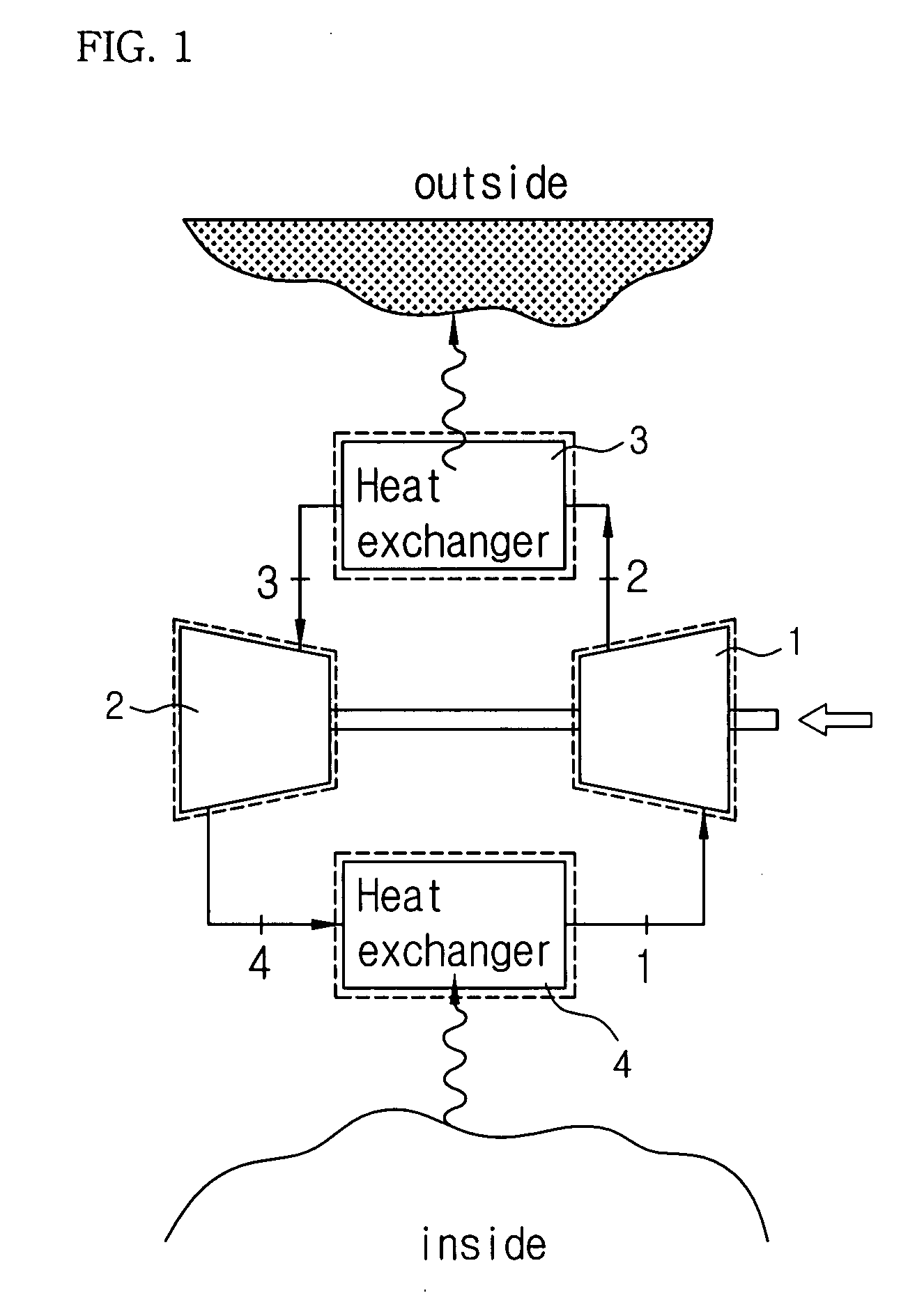
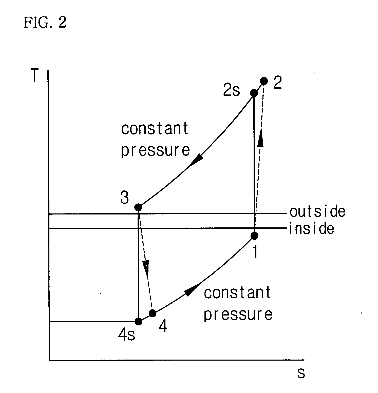
BACKGROUND OF THE INVENTION[0001]1. Field of the Invention[0002]The present invention relates to an air compressor and expander, and more particularly, to an air compressor and expander that is capable of preventing the generation of clearance between end covers and rotors in an air cycle during which air is compressed and expanded, thereby improving refrigerating effects.[0003]2. Background of the Related Art[0004]As the global warming and environmental problems become severe, recently, so as to replace a refrigerant like R-134a as used up to now with new refrigerant, many endeavors for developing alternative refrigerant systems have been made by all the refrigeration companies over the world, and especially, they have studied on a new system that is environment-friendly and has a high refrigerating efficiency, without any replacement of the refrigerant itself.[0005]An air cycle that is recently considered as a most effective alternative cycle is called a reverse Bryton air cycle, ...

Claims


Application Information

Patent Timeline
IPC IPC(8): F01C1/00F25D9/00
CPCF01C1/16F01C11/004F01C21/06F25B9/004F04C2230/601F05C2225/04F04C29/0071F04C2/14F04C18/16
Inventor LEE, JUNKANG
Owner HALLA CLIMATE CONTROL
Learn More