
Riving knife clamp for a table saw

a technology of a table saw and a clamping device, which is applied in the direction of metal sawing devices, sawing devices, sawing apparatus, etc., can solve the problems of reducing the possibility of workpiece kickback, high probability of accidents and injuries, and complex assembly

Inactive Publication Date: 2007-08-16
EASTWAY FAIR OF TRIDENT CHAMBERS
View PDF66 Cites 57 Cited by
  • Summary
  • Abstract
  • Description
  • Claims
  • Application Information

AI Technical Summary

Benefits of technology

[0004] A table saw is provided that includes a table with an aperture to receive a portion of a rotatable saw blade that extends from below the table and a riving knife that extends through the aperture from below the table. The riving knife includes a slot that receives a first pin to retain the riving knife in a selected position with respect to the saw blade and the riving knife includes a plurality of recesses. A cam is additionally provided and is supported by the table. The cam is rotatable and operatively connected with the first pin such that when the cam is in a first position the riving knife may be retained in a selective position and when the cam is in a second position the riving knife is movable to another selective position. The cam additionally may cause movement of a second pin that may be received within one of the plurality of recesses.

Problems solved by technology

The arrangement of the table saw with a riving knife reduces the possibility of workpiece kickback.
However, these assemblies have often been difficult to use because they are typically flimsy or obstruct the operator's view of the workpiece with respect to the saw blade, or reference marks or scales used to align the workpiece.
As a result, many users remove the guard and the riving knife while operating the table saw, which results in a higher probability of accidents and injuries.
Additionally, the removal and replacement of the guard and the riving knife often requires multiple procedural steps that make the process of removing and replacing these components complicated and difficult, such that the user often removes these components for a specific project and never replaces them.

Method used


Image

  • Riving knife clamp for a table saw
  • Riving knife clamp for a table saw
  • Riving knife clamp for a table saw

Examples


Embodiment Construction

[0022] While this invention is susceptible of several different embodiments, this specification and the accompanying drawings disclose only some specific forms as examples of the invention. The invention is not intended to be limited by the descriptions in this specification or the drawings. Instead, the scope of the invention is provided in the claims.

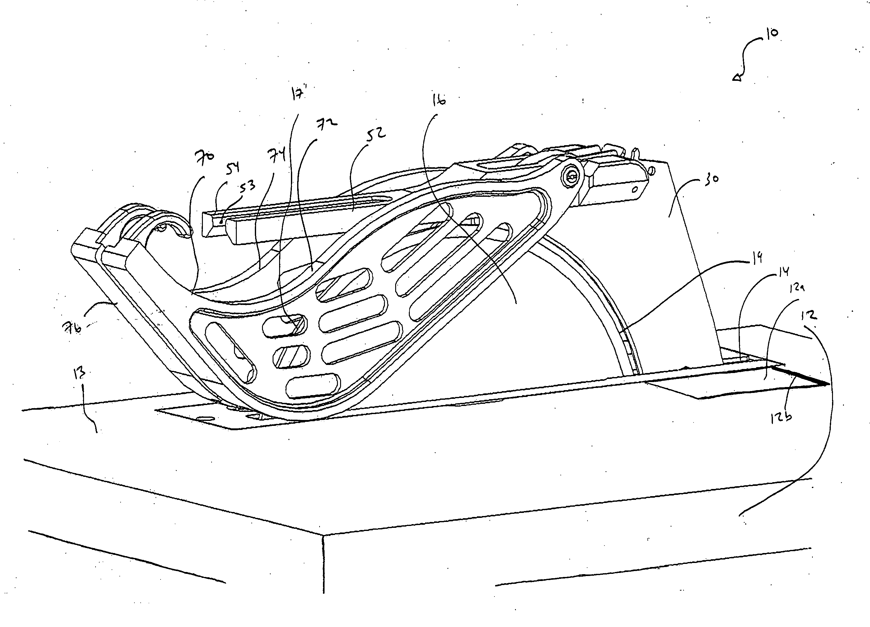
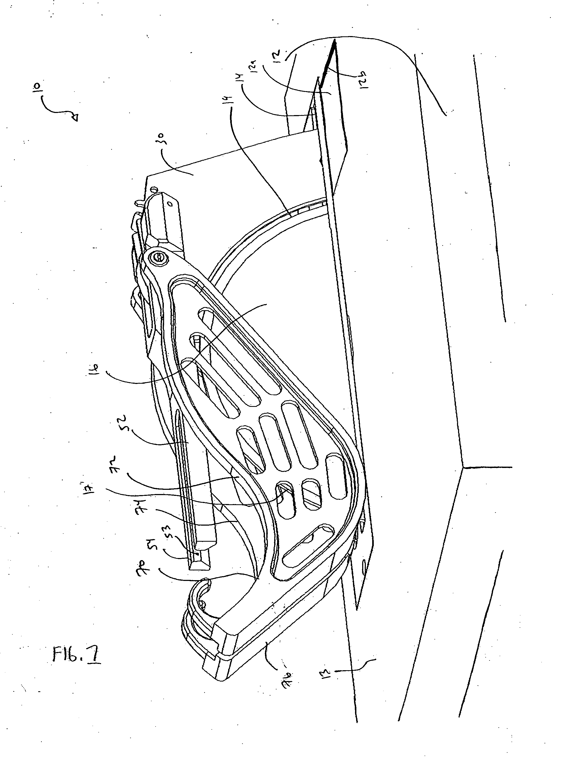
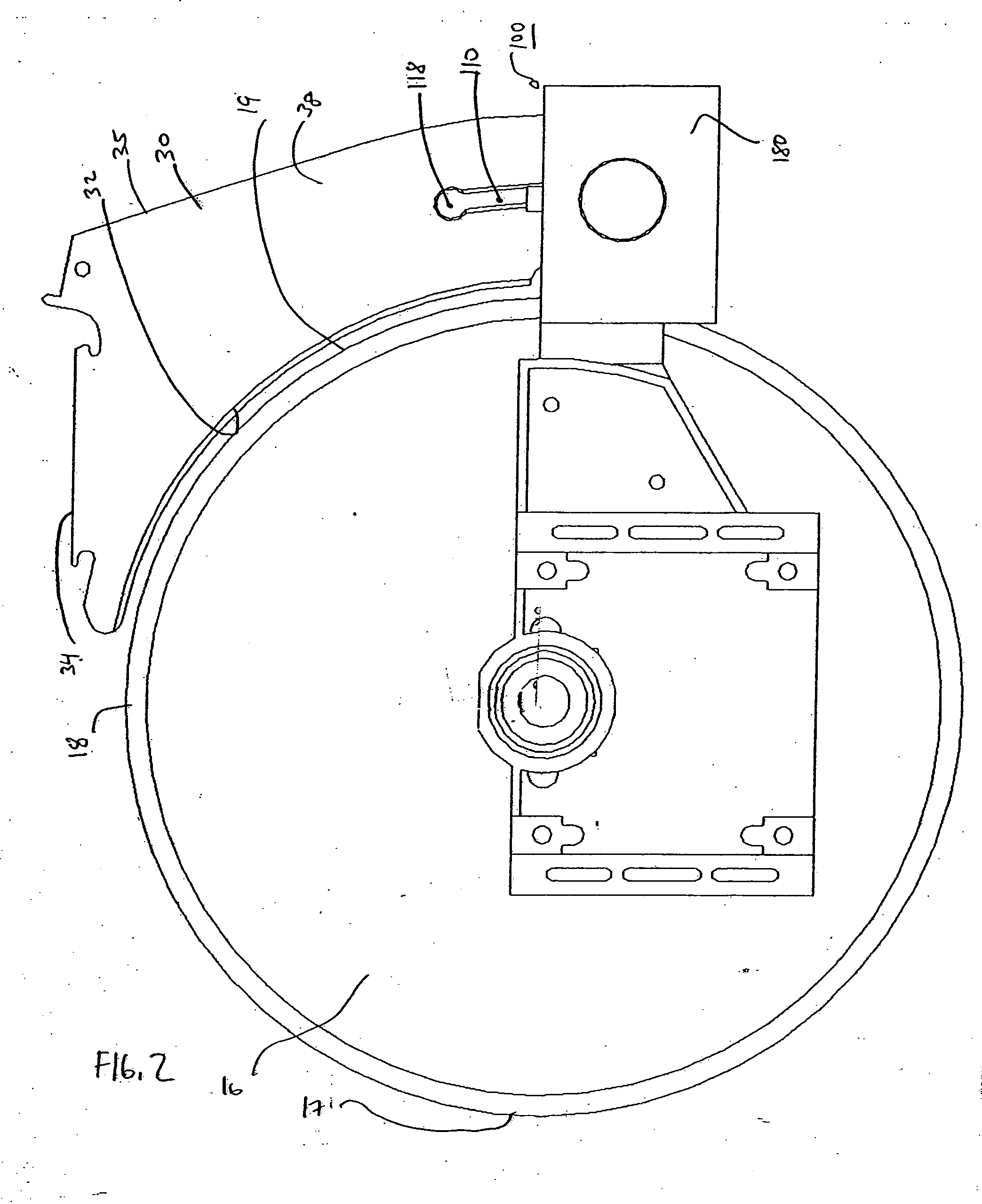
[0023] Turning now to FIGS. 1-9, a table saw 10 having one embodiment of the inventive riving knife / guard assembly is provided. The table saw 10 includes a table 12 with a top surface 13. The table 12 includes a slot, or aperture, 14 that extends through the table 12. A saw blade 16 is conventionally mounted to a motor and carriage (both not shown) that is located under the table 12. A portion of the saw blade 16 protrudes through the slot 14. The portion of the blade 16 that protrudes through the slot 14 is the operative portion for cutting a workpiece (not shown). The knife / guard assembly 20 includes a riving knife, or splitter 30,...


PUM

PropertyMeasurementUnit
Forceaaaaaaaaaa
Angleaaaaaaaaaa
Diameteraaaaaaaaaa

Abstract

A table saw comprising a table including an aperture to receive a portion of a rotatable saw blade extending from below the table and a riving knife extending through the aperture from below the table. The riving knife includes a slot that receives a first pin and the riving knife includes a plurality of recesses. A cam that operatively engages the first pin and is rotatable to cause linear motion of the first pin with respect to the slot such that when the cam is in a first position the riving knife may be retained in a selected position and when the cam is in a second position the riving knife may be movable to another selected position, wherein the rotation of the cam additionally causes movement of a second pin that may be received within one of the plurality of recesses.

Description

BACKGROUND [0001] Typical table saws include a base or frame having a flat table top or supporting a flat table top. The table top generally includes a slot through which a cutting member, such as a circular saw, protrudes above the table top. Often, a riving knife, or splitter, is mounted directly in-line with the saw blade. The riving knife operates to keep the two portions of the workpiece that have been cut separate to prevent the workpiece from binding on the saw blade. The arrangement of the table saw with a riving knife reduces the possibility of workpiece kickback. Many table saws also include a guard to protect the operator from potentially serious injury caused by accidental contact with the saw blade. The guard is provided to prevent the operator from contacting the saw blade while in use. [0002] Many types of riving knives and guard assemblies have been used in the past. However, these assemblies have often been difficult to use because they are typically flimsy or obstr...

Claims


Application Information

Patent Timeline
IPC IPC(8): B23D45/06
CPCB27G19/08Y10T83/773Y10T83/2077
Inventor PEOT, DAVID G.BUCK, WILLIAM C.
Owner EASTWAY FAIR OF TRIDENT CHAMBERS
Learn More