Dual lift rocker arm latch mechanism and actuation arrangement therefor

a latch mechanism and rocker arm technology, applied in the direction of mechanical control devices, controlling members, instruments, etc., can solve the problems of increasing the cost of the overall valve control system, requiring much more space for “packaging”, and affecting the design of the rocker arm assembly, so as to achieve the effect of substantial cost, weight, and structur

Active Publication Date: 2007-08-16
EATON INTELLIGENT POWER LIMITED
View PDF5 Cites 63 Cited by
  • Summary
  • Abstract
  • Description
  • Claims
  • Application Information

AI Technical Summary

Benefits of technology

[0010] It is a more specific object of the present invention to provide such an improved dual lift rocker arm assembly in which the latching mechanism is controlled by pressurized fluid fr

Problems solved by technology

Although such electromagnetic actuation of the latching mechanism has been found to operate in a generally satisfactory manner, the resulting need for a separate electromagnetic actuator for each rocker arm assembly would add substantially to the cost of the overall valve control system, and in many applications, would require much more space for “packaging” than is available in the typical engine cylinder head.
Although the rocker arm assemblies of the above-incorporated patents, in the immediately preceding paragraph, do provide at least the potential for substantially improved actuation of the latching mechanism, the need to communicate the low pressure (control) fluid from the lash adjuster to the latching mechanism has somewhat complicated the design of the rocker arm assembly.
Unfortunately, in the

Method used


Image

  • Dual lift rocker arm latch mechanism and actuation arrangement therefor
  • Dual lift rocker arm latch mechanism and actuation arrangement therefor
  • Dual lift rocker arm latch mechanism and actuation arrangement therefor

Examples


Embodiment Construction

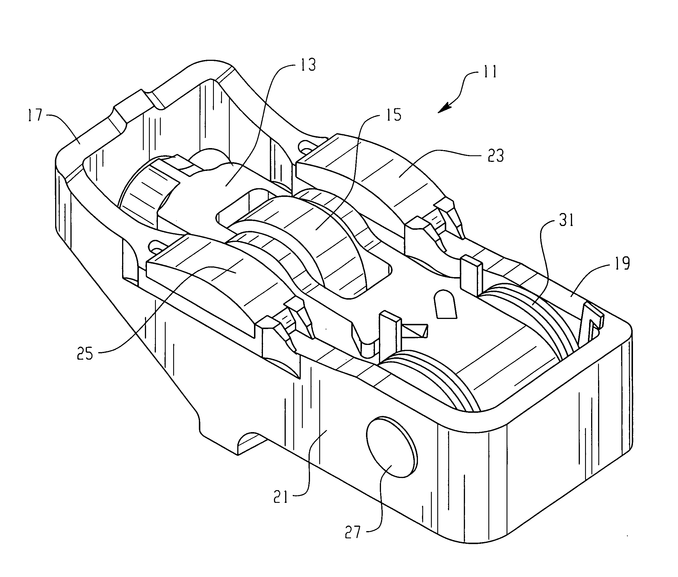
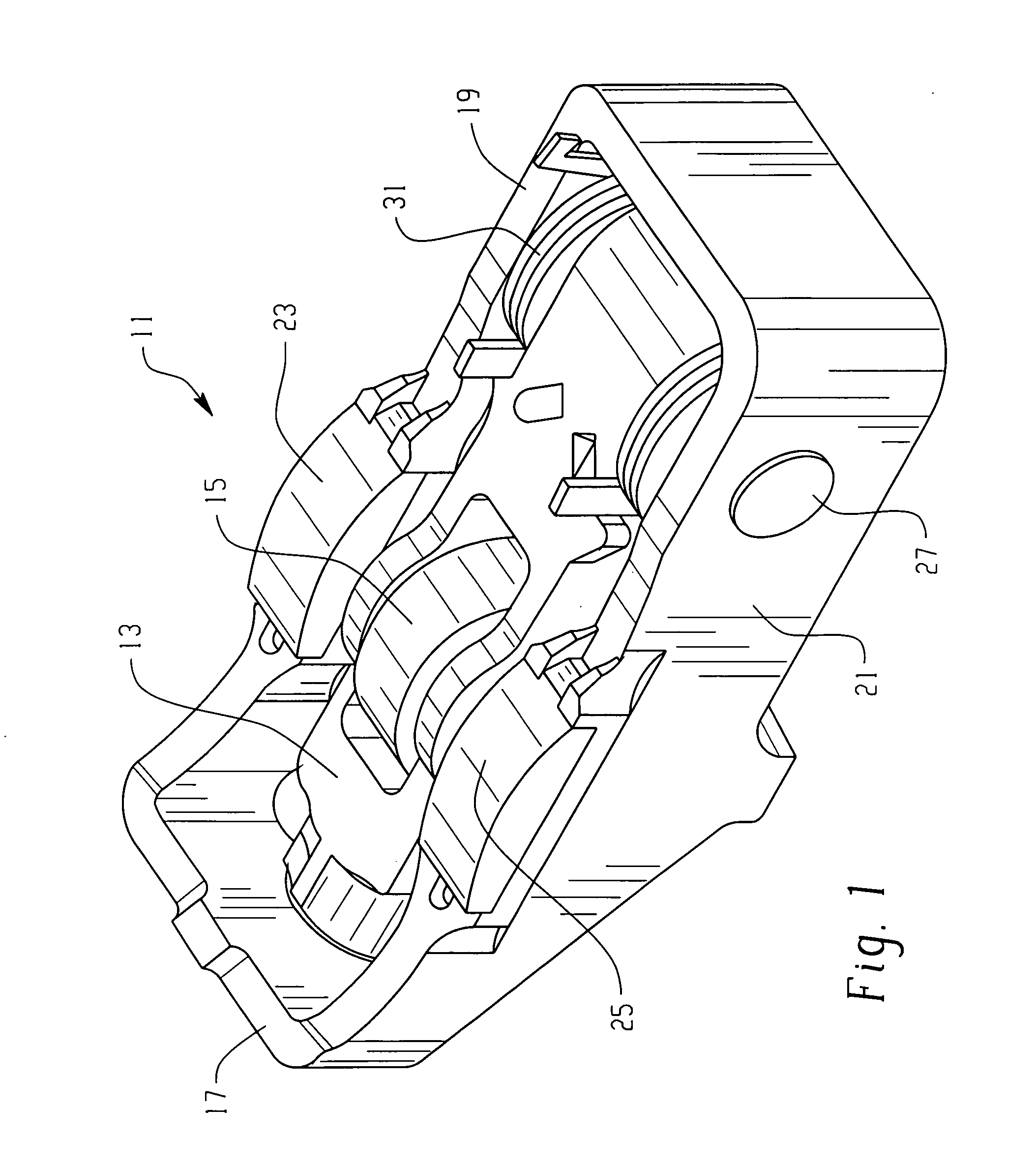
[0019] Referring now to the drawings, which are not intended to limit the invention, FIG. 1 illustrates a dual lift rocker arm assembly, generally designated 11, of the general type illustrated and described in U.S. Pat. No. 5,655,488, assigned to the assignee of the present invention and incorporated herein by reference. One reason for referring to the incorporated patent is that it shows the cam shaft, including the high lift and low lift cam profiles, as well as a portion of the cylinder head, and also shows the engine poppet valve, none of which are illustrated herein, for the sake of simplicity, and because such elements are well known to those skilled in the art, and do not require detailed description.

[0020] Referring still to FIG. 1, the dual lift rocker arm assembly 11 of the present invention comprises an inner rocker arm 13 (also referred to hereinafter in the appended claims as a “first” rocker arm). The inner rocker arm 13 includes a roller follower 15 which, in the su...


PUM


Abstract

A valve control system including a camshaft having first and second cam profiles, the valve control system comprising a rocker arm assembly (11) including a first rocker arm (13) having a first cam follower (15) in engagement with the first cam profile, and a second rocker arm (17) having a second cam follower (23,25) in engagement with the second cam profile. The engine includes a fulcrum location (P) operable to provide a source of pressurized fluid, and the first rocker arm includes a latch member (47) moveable between latched (FIG. 6) and unlatched conditions. The latch member is biased toward the latched condition by a fluid pressure in a chamber (51), and the first rocker arm defines a fluid passage (55) having a first end (57) in open fluid communication with the pressure source, and a second end (59) in open fluid communication with the pressure chamber (51).

Description

BACKGROUND OF THE DISCLOSURE [0001] The present invention relates to valve control systems for internal combustion engines of the type in which the movement of an engine poppet valve is controlled in response to rotation of a cam shaft, and more particularly, to such a valve control system in which the cam shaft has a cam profile including both a high lift portion and a low lift portion. [0002] Even more specifically, the present invention relates to such a valve control system including a dual lift rocker arm assembly of the type having both a high lift cam follower and a low lift cam follower (for engagement with the high lift portion and the low lift portion, respectively, of the cam profile). Although the terms “high lift” and “low lift” can have various meanings when used in regard to valve control systems for engine poppet valves, it should be understood that, within the scope of the present invention, all that is required is that one cam profile provide a relatively higher li...

Claims


Application Information

Patent Timeline
IPC IPC(8): F01L1/34F01L1/02F01L1/18
CPCF01L1/185Y10T74/20882F01L13/0036F01L13/0005F01L2001/186F01L13/00F01L1/18
Inventor ZURFACE, AUSTIN R.HARMAN, ANDREW P.CHURCH, KYNAN L.
Owner EATON INTELLIGENT POWER LIMITED
Why Eureka
Try Eureka