
Eureka
For R&D, Eureka makes reading and utilizing patents & technical documents easy.
Eureka AIR
Designed for self-driven R&D workflows. Generate viable solutions, solve complex R&D challenges, empower your innovation with AI.

Eureka Materials
Designed for material experts only. Revolutionize your material R&D, from search, analyze, to developing new materials.

TechResearch
Generate reliable direction feasibility study reports for your R&D in just a few steps.

TechSeek
Discover and master advanced knowledge NOW. Basics, ideas, possibilities, all at once.

TechMind
As an expert in R&D Theories, TechMind can generates customized viable solutions instantly.

TechRisk
Analyze your overall solution with one click, know your potential R&D risks in advance.

TechMonitor
Get weekly tech updates, stay abreast of the latest tech innovations and key insights.
Fuel cutoff valve
- Summary
- Abstract
- Description
- Claims
- Application Information
AI Technical Summary
Benefits of technology
Problems solved by technology
Method used
Image

Examples
Embodiment Construction
[0025](1) General Arrangement of Fuel Cutoff Valve 10
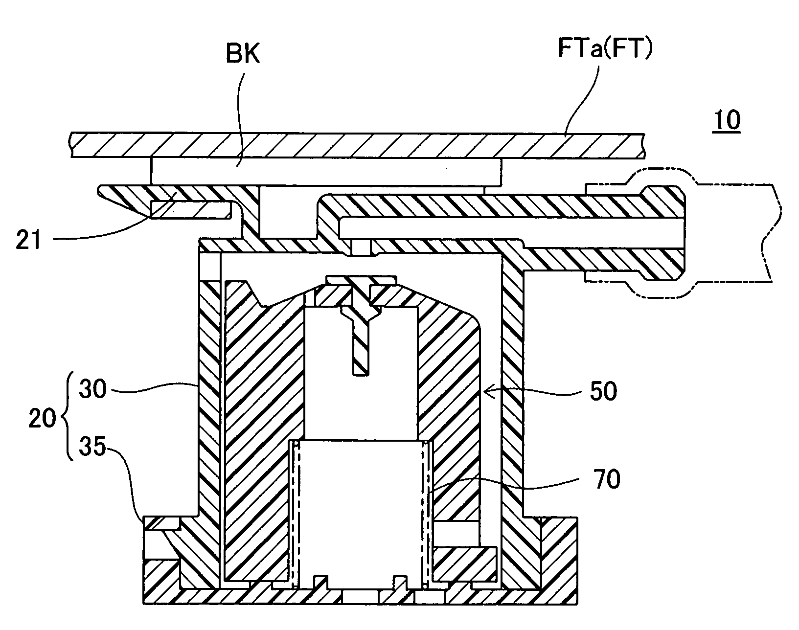
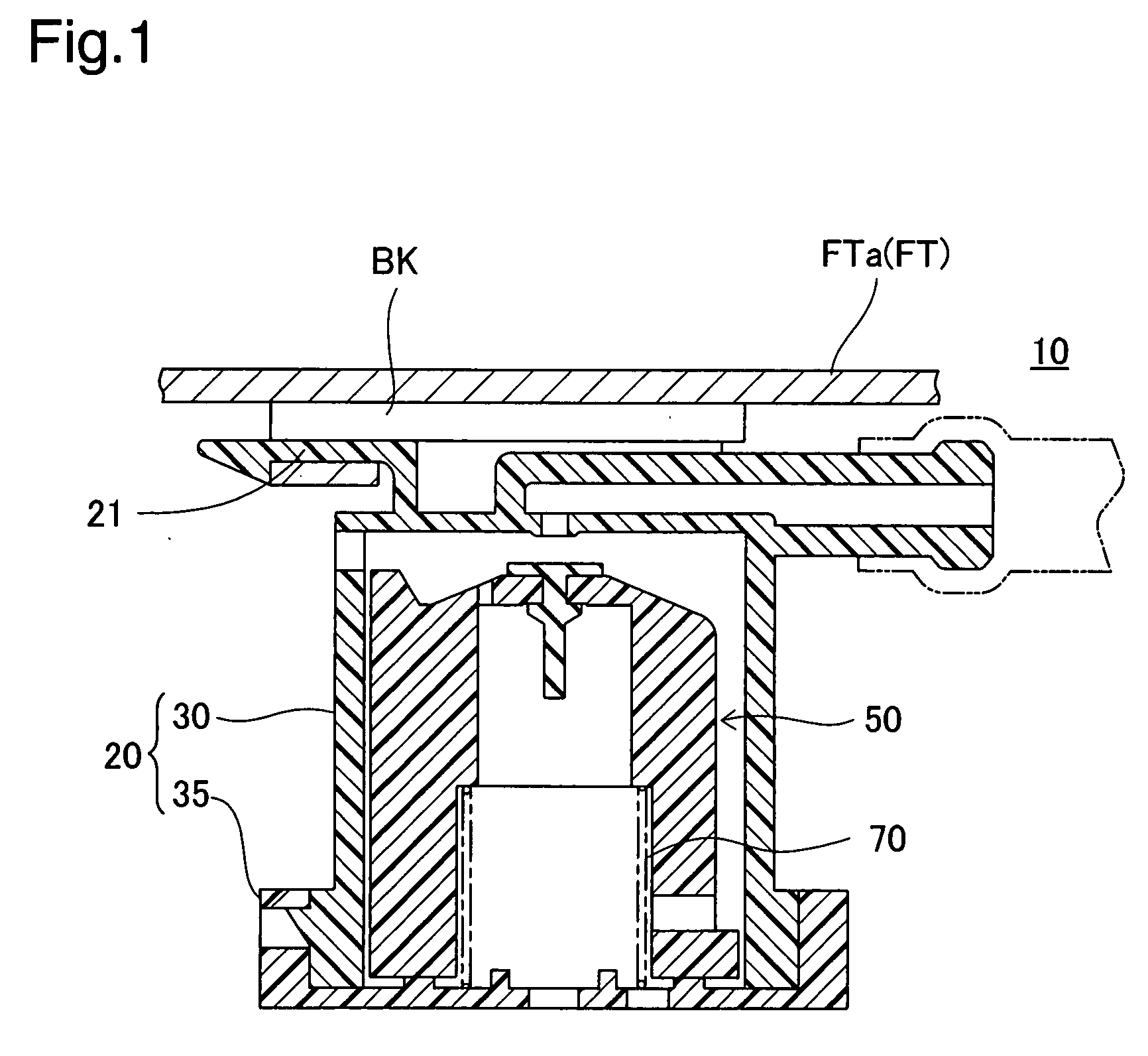
[0026]FIG. 1 is a sectional view showing a fuel cutoff valve 10 attached to the upper part of a fuel tank FT of an automobile in one embodiment of the invention. The fuel cutoff valve 10 is of so-called in-tank type installed inside the fuel tank FT. The fuel cutoff valve 10 functions as a valve for preventing fuel from flowing to the outside in the event of a rise in fuel level within the fuel tank FT when the vehicle inclines or turns rapidly for example. The fuel cutoff valve 10 comprises as its principal parts a casing 20, a float mechanism 50, and a spring 70. A valve mounting portion 21 is integrally formed in the upper part of the casing 20 and is attached to the inside of the fuel tank FT via a bracket BK which is welded to the lower face of a tank upper wall FTa of the fuel tank FT.
[0027](2) Arrangement of Fuel Cutoff Valve 10 Parts
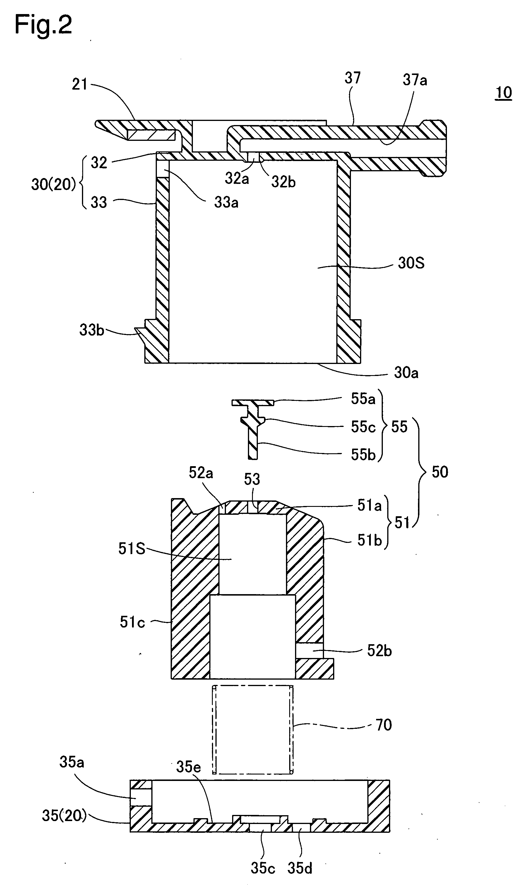
[0028]FIG. 2 is an exploded sectional view of the fuel cutoff valve. In FIG. 2, the casing ...
PUM
 Abstract
Description
Claims
Application Information
 - R&D Engineer
- R&D Manager
- IP Professional
- Industry Leading Data Capabilities
- Powerful AI technology
- Patent DNA Extraction
Browse by: Latest US Patents, China's latest patents, Technical Efficacy Thesaurus, Application Domain, Technology Topic, Popular Technical Reports.
© 2024 PatSnap. All rights reserved.Legal|Privacy policy|Modern Slavery Act Transparency Statement|Sitemap|About US| Contact US: help@patsnap.com