Power generating device

Inactive Publication Date: 2007-08-16
CHANG ERNIE
View PDF3 Cites 1 Cited by
  • Summary
  • Abstract
  • Description
  • Claims
  • Application Information

AI Technical Summary

Benefits of technology

[0007] The primary objective of the present invention is to provide a power generating device input with a small power to make a gravity press

Problems solved by technology

However, no matter which of the methods including wind power, water power, earth heat or solar energy etc. is used to generate electric energy, the methods have regional limitations; for instance, some areas have weak wind power for years generally, they ar

Method used


Image

  • Power generating device
  • Power generating device
  • Power generating device

Examples


first embodiment

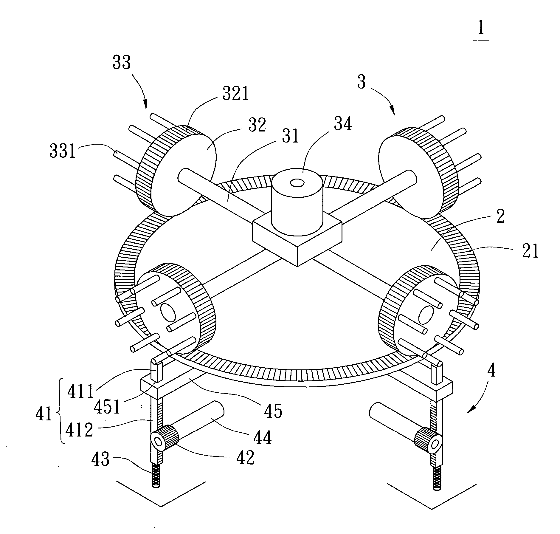
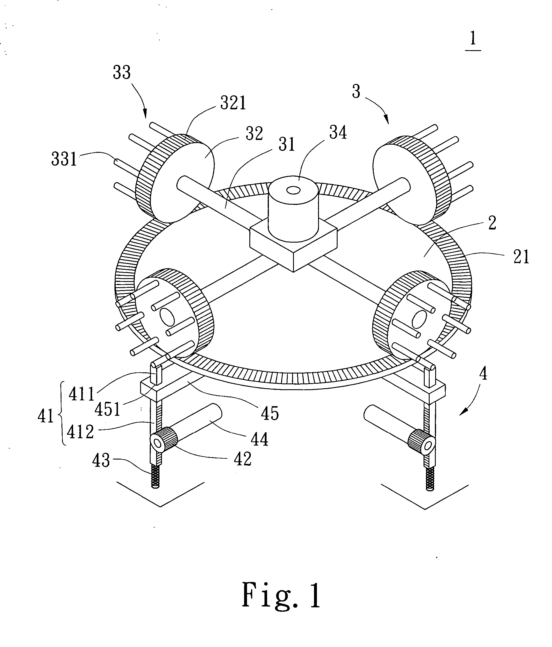
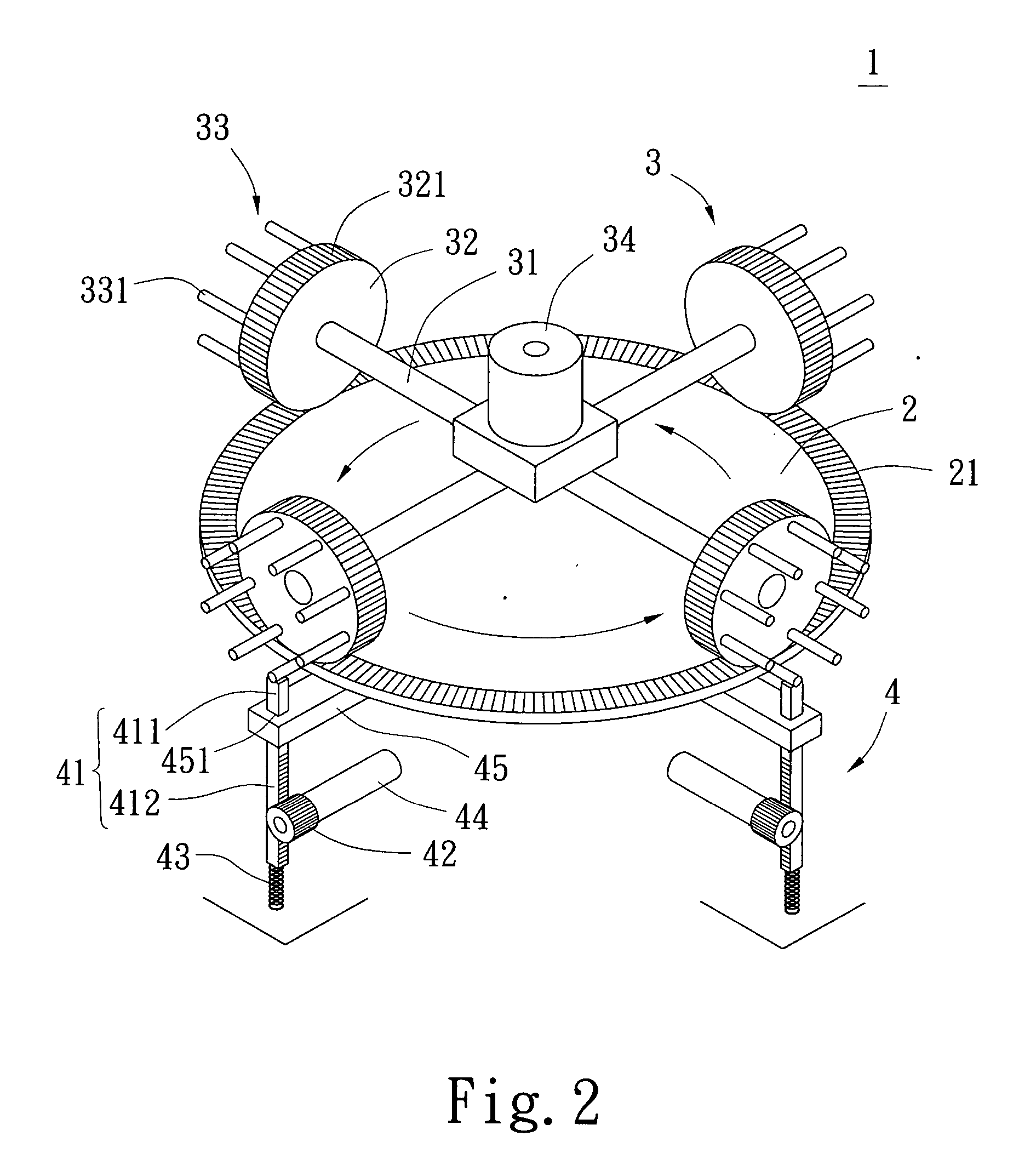
[0020] Referring firstly to FIG. 1 showing a power generating device 1 of the present invention, the power generating device comprises a base 2, at least a gravity pressurizing device 3 and at least a moving-to-and-fro linking member 4.

[0021] The base 2 is a fixed round disc, its upper disc surface is provided on its periphery with a first engaging portion 21; the first engaging portion 21 is composed of multiple protruding teeth.

[0022] In this embodiment, the number of all the gravity pressurizing devices 3 is four; each gravity pressurizing device 3 includes an axle rod 31 and a restraining and pressing portion 33, the restraining and pressing portion 33 includes a roller 32 and a plurality of restraining and pressing rods 331, the restraining and pressing rods 331 are combined on a lateral surface of the roller 32 and are arranged in a circle. One end of the axle rod 31 is connected to a power inputting device 34 to drive the gravity pressurizing device 3 to roll on the base 2; ...

second embodiment

[0032] Referring to FIGS. 7-9 showing a schematic view of the power generating device 1 of the present invention, wherein the moving-to-and-fro linking member 6 (8) further includes an upper linking plate 92 and a lower linking rod 93, two ends of the upper linking plate 92 are pivotally connected respectively to the base 2 and the lower linking rod 93, while the lower end of the lower linking rod 93 is pivotally connected to the push-pressing portion 411 (611); the upper linking plate 92 has an elevation angle to the base 2. When the roller 32 rolls on the upper disc surface of the base 2, by the heavy pressure exerted on the base 2 by the roller 32, the upper linking plate 92 pushes the lower linking rod 93 and the push-pressing portions 411 and 611 downwards to thereby move the moving-to-and-fro linking members 6, 8 to output power.

third embodiment

[0033] Referring to FIG. 9 showing a schematic view of the power generating device 1 of the present invention, wherein a gravity pressuring device 7 is preferably a metallic round disc, the periphery of the bottom surface of the round disc 7 has a plurality of magnetic down protruding parts 71 arranged in a circle, the down protruding parts 71 are used as a restraining and pressing portion. A push-pressing portion 811 of a slide member 81 on a moving-to-and-fro linking member 8 is provided thereon with a magnetic up protruding part 812, the down protruding parts and the up protruding part 71, 812 are magnets of the same polarity. The gravity pressuring device 7 and a base 9 are provided therebetween with a plurality of rollers 91 to reduce the friction force between the gravity pressuring device 7 and the base 9 during rolling. Therefore, when the gravity pressuring device 7 is rotated on the base 9, the down protruding parts and the up protruding part 71, 812 push the push-pressing...


PUM


Abstract

A power generating device comprising at least a gravity pressurizing device rotatably connected to a base, the power generating device has on its one end a restraining and pressing portion; when the gravity pressuring device is rotated on the base, it pushes the push-pressing portion on one end of a moving-to-and-fro linking member to render moving of the moving-to-and-fro linking member, a power outputting portion on the other end of the moving-to-and-fro linking member outputs energy for supplying energy source for various power equipment.

Description

BACKGROUND OF THE INVENTION [0001] 1. Field of the Invention [0002] The present invention relates to a power generating device which is structurally simple, convenient for operation and cost low. And more particularly to a power generating device input with a small power to make a gravity pressurizing device exert pressure on a moving-to-and-fro linking member for generating stable large power output. The present invention is suitable for supplying energy source for various power equipment. [0003] 2. Description of the Prior Art [0004] In recent years, because of the crisis that the energy source of gasoline is going to be exhausted, countries all over the world actively develop the methods to generate electric energy by using the natural resources of wind power, water power, earth heat or solar energy etc. to reduce the speed of exhausting [0005] However, no matter which of the methods including wind power, water power, earth heat or solar energy etc. is used to generate electric e...

Claims


Application Information

Patent Timeline
IPC IPC(8): F03G3/00
CPCF03G3/00
Inventor CHANG, ERNIE
Owner CHANG ERNIE
Why Eureka
Try Eureka