Filter housing and parts therefor

a filter housing and filter technology, applied in the direction of filtering separation, moving filter element filters, separation processes, etc., can solve the problems of unknown filter housings, suffer from various problems and disadvantages, and the interior wall of the housing does not promote highly efficient filtration, so as to achieve greater radial distance and enhance filtration efficiency

Inactive Publication Date: 2007-08-16
HAYWARD IND INC
View PDF18 Cites 26 Cited by
  • Summary
  • Abstract
  • Description
  • Claims
  • Application Information

AI Technical Summary

Benefits of technology

[0008] The present invention overcomes the disadvantages and shortcomings discussed above. In accordance with a feature of the present invention, a filter housing is provided with a greater annular space between an inner wall of the housing and a filter cartridge. More particularly, the filter housing of the present invention is larger than conventional housings, including a greater radial distance from the housing wall to the filter, which promotes the creation of fluid turbulence within the filter housing. The fluid turbulence more evenly disperses the particles in an unfiltered fluid, thereby enhancing filtration efficiency by causing filtering to occur along the substantially entire area of the filter cartridge.
[0009] In accordance with another feature of the present invention, an improved pressure relief valve is provided. The valve may be quickly opened to vent excess air in the housing by rotating a lever. The top of the housing acts as a stop for preventing further rotation of the lever. The valve has a simple construction, making it more economical to manufacture and simpler to use.
[0010] Yet another feature of the present invention relates to a securing or locking ring which is integrated with a cover of the filter housing. The securing ring simplifies removal of the cover from a base of the filter housing, and also ensures secure placement thereon. Handles and latch assemblies on the securing ring are deployed to threadably engage or disengage the cover from the base.

Problems solved by technology

Known filter housings, such as the one disclosed in U.S. Pat. No. 6,217,754, suffer from various problems and disadvantages.
For instance, the proximity of the filter cartridge to the interior wall of the housing does not promote highly efficient filtration.
More particularly, limited annular space between the filter and the housing wall may prevent turbulent flow of the unfiltered fluid within the filter housing, resulting in an unevenly dispersed mixture of particles and an aggregation of particles settling at the bottom of the filter.
Swimming pool filter housings are also known to accumulate compressed air, which can lead to excess pressure in the housing, causing its components to violently separate or require disassembly.
Conventional relief valves, typically petcock-type valve devices, suffer from various problems and disadvantages.
The valve stem can be unscrewed from the valve housing too far, to the point where it falls out of the housing, causing an interruption in the bleeding operation until the valve stem is located and replaced.
Another problem with conventional petcock-type valves is that the rate of air bled through the valve depends on the degree to which the stem is unscrewed.
This causes inefficient valve bleeding as well, since the petcock has to be opened as far as possible to vent the housing quickly, but such opening could take an unsatisfactory lengthy amount of time.
However, the complicated structure and multiple components of the relief valve disclosed in U.S. Pat. No. 5,435,339 render it impractical and expensive to manufacture.
Another problem encountered in conventional filter housings involves the securing rings used to attach the top component, or cover, to the bottom component, or base.
This structural arrangement (i.e., a securing ring not integrated with the cover) both complicates operation of the filter housing, and compromises the efficiency thereof.

Method used


Image

  • Filter housing and parts therefor
  • Filter housing and parts therefor
  • Filter housing and parts therefor

Examples


Embodiment Construction

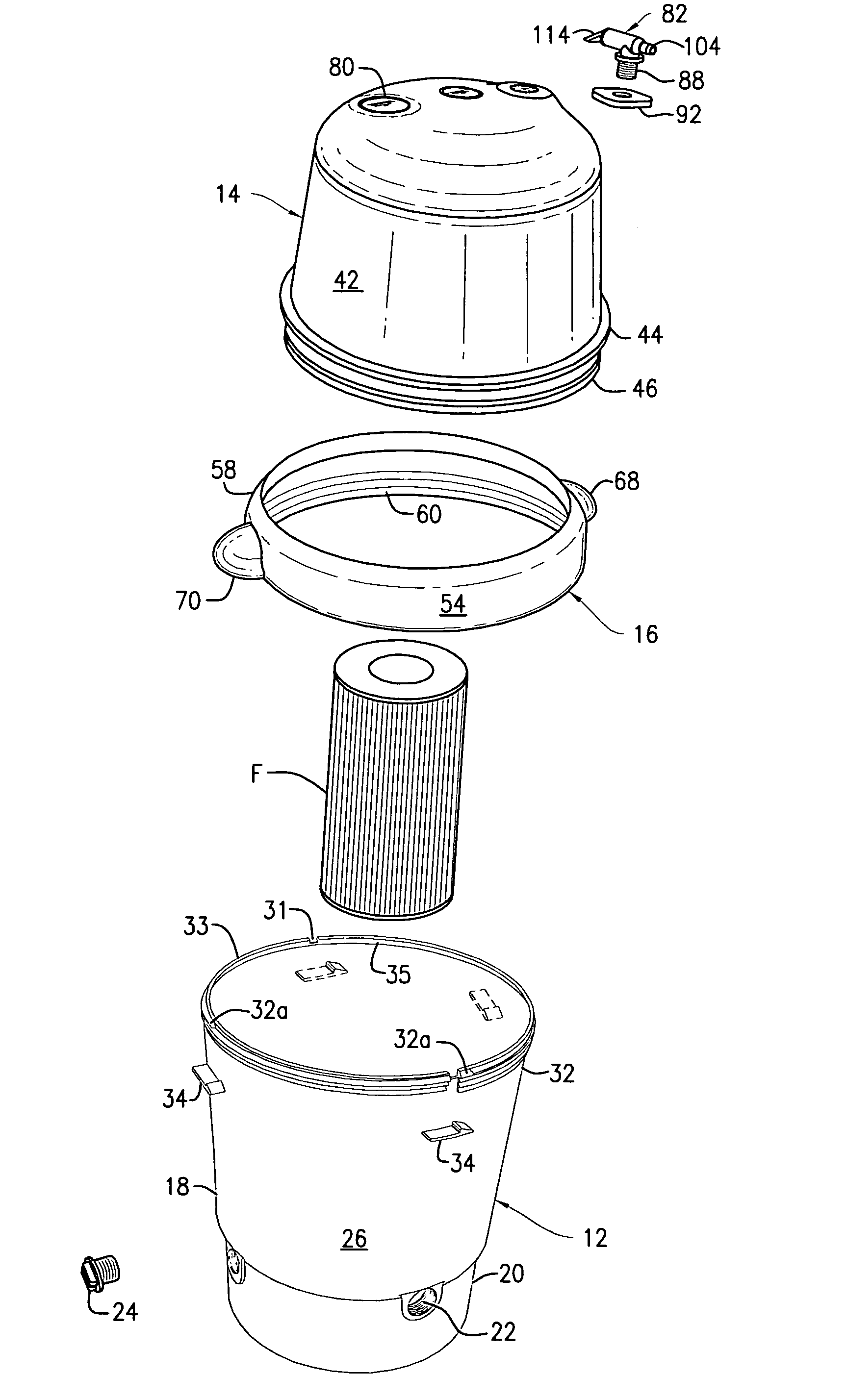
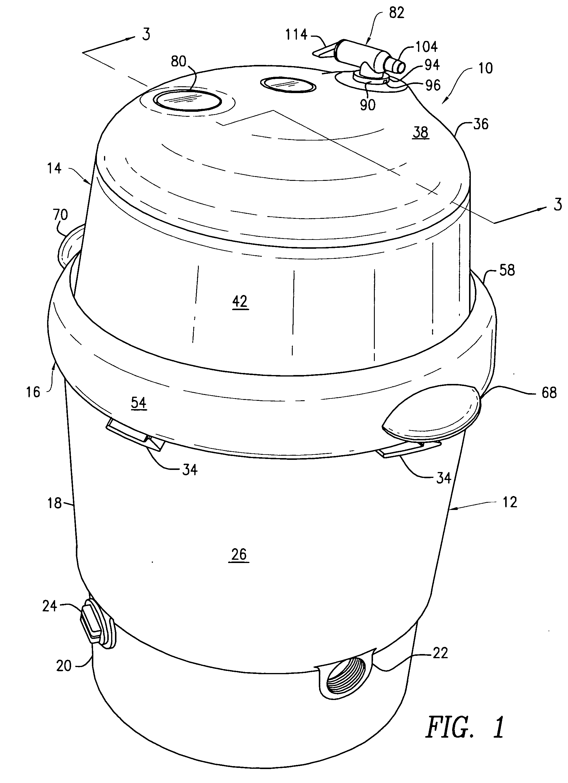
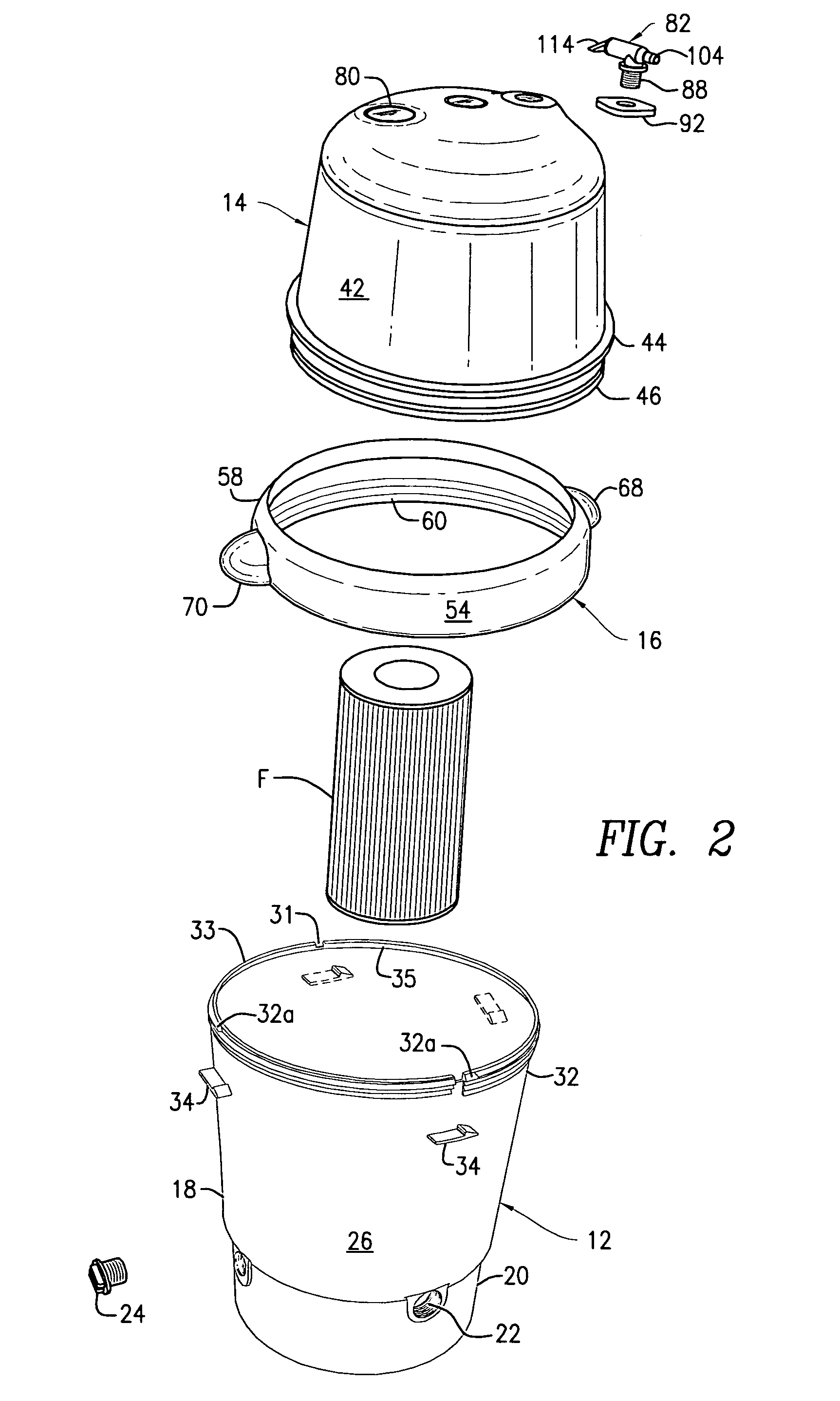
[0025]FIGS. 1-3 and 5 illustrate a filter housing 10 constructed in accordance with the present invention. The filter housing 10 includes a base 12 and a cover 14 which has an integral securing or locking ring 16 for removeably securing the cover 14 to the base 12. The base 12 is rounded, with a generally oval cross section as a result of the machining process and the materials used. The base 12 has an upper portion 18 and a lower portion 20. The lower portion 20 has standard filter housing features, including an outlet 22, an inlet (not shown) and a drain plug 24. The upper portion 18 comprises an annular wall 26 and a floor 28 (see FIG. 3), which separates the upper portion 18 from the lower portion 20. A hollow vertical support 30 extends upwardly from the floor 28, and may be integrally formed therewith so as to be in communication with the outlet 22 (see FIG. 3). The vertical support 30 is sized and shaped so as to receive a bottom opening of a cartridge filter F thereon. The u...


PUM

PropertyMeasurementUnit
pressureaaaaaaaaaa
flexibleaaaaaaaaaa
diameteraaaaaaaaaa

Abstract

A filter housing is provided for use with swimming pool filtration systems. The housing has an enlarged interior annular space between the housing wall and the filter, so as to facilitate the creation of fluid turbulence within the housing, which promotes more efficient filtration. The housing includes a base, a cover and a securing ring which is integrally attached to the cover and which facilitates the removal and attachment of the cover to the base. The cover is also provided with an improved pressure relief valve that has a lever which is rotated to open the valve quickly and vent excess air in the housing. The housing acts as a stop for preventing further rotation of the lever.

Description

CROSS REFERENCE TO RELATED APPLICATION [0001] This application claims priority of U.S. Provisional Patent Application Ser. No. 60 / 733,440, filed Nov. 3, 2005, the disclosure of which is incorporated by reference herein in its entirety.FIELD OF THE INVENTION [0002] The present invention relates to filter housings and, more particularly, to filter housings having features which enhance filtration and facilitate handling and maintenance of swimming pool filtration systems. BACKGROUND OF THE INVENTION [0003] Various types of filter housings have been developed in the past for use in swimming pools. For instance, one type of filter housing is designed for use with a cartridge-type filter. Examples of such cartridge-type filter assemblies with filter housings are disclosed in U.S. Pat. Nos. 4,617,117, 5,871,641 and 6,217,754. [0004] Known filter housings, such as the one disclosed in U.S. Pat. No. 6,217,754, suffer from various problems and disadvantages. For instance, the proximity of th...

Claims


Application Information

Patent Timeline
Patent Type & Authority Applications(United States)
IPC IPC(8): B01D35/00
CPCB01D35/30B01D36/001B01D2201/4076B01D2201/304B01D2201/4015B01D2201/302
Inventor PECCA, JEFFREY P.
Owner HAYWARD IND INC
Why Eureka
Try Eureka