
Steering apparatus for a vehicle

Inactive Publication Date: 2007-08-16
TOYOTA JIDOSHA KK
View PDF16 Cites 16 Cited by
  • Summary
  • Abstract
  • Description
  • Claims
  • Application Information

AI Technical Summary

Benefits of technology

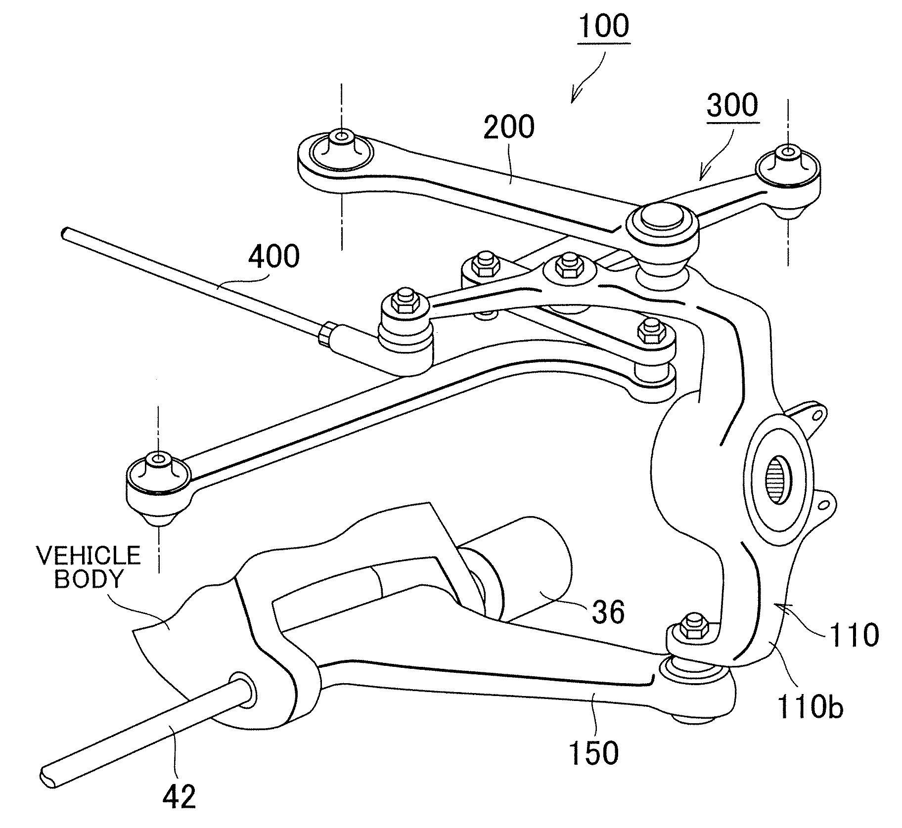
[0007]The present invention has an object to provide a steering apparatus for a vehicle that is capable of achieving a turning angle characteristics with high steering efficiency, regardless of the steering direction.
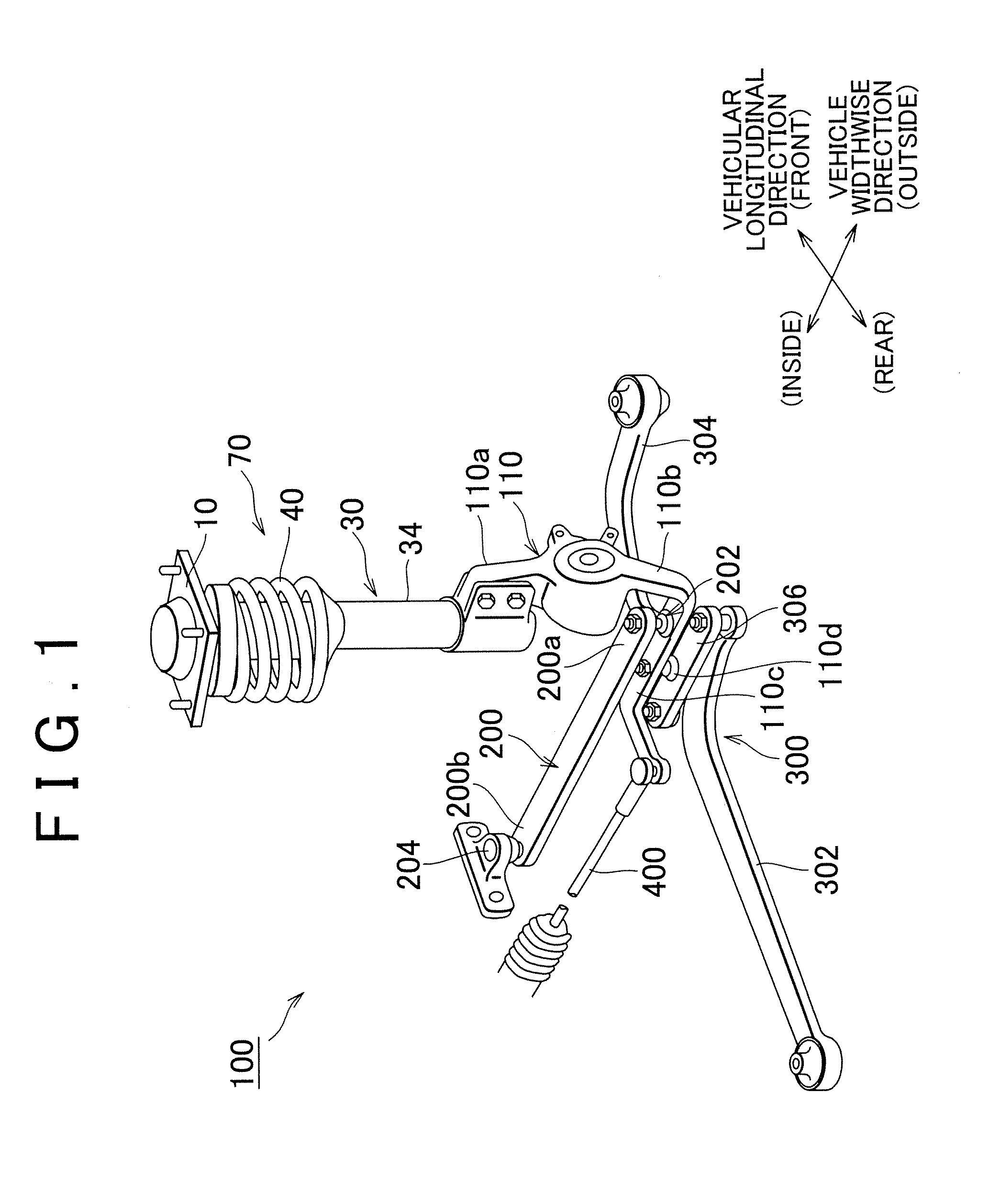
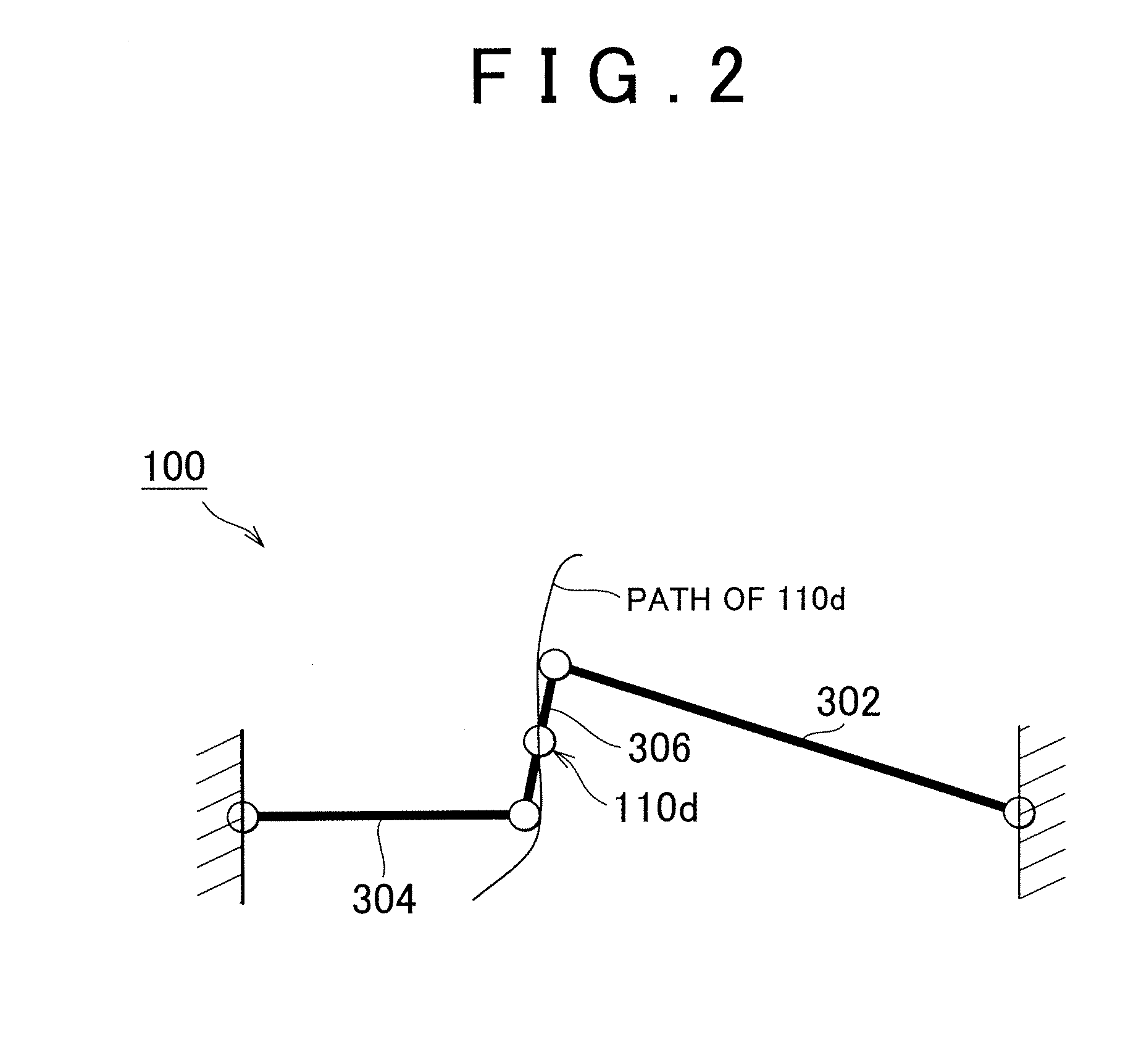
[0010]By doing this, because the difference in the movement mode of the first pivot point of the wheel support member due to a difference in the steering direction of the wheel is eliminated, it is possible to achieve a proper tire turning angle regardless of the steering direction.
[0014]By doing this, because the difference in the movement of the first pivot point of the wheel support member due to a difference in the steering direction of the wheel is eliminated, it is possible to achieve a proper tire turning angle regardless of the steering direction.
[0015]In the above-described steering apparatus for a vehicle, in association with movement of the first pivot point of the wheel support member outward in the vehicle width direction, the inclination of the kingpin axis may be changed to the vertically standing direction. By doing this, it is possible to reduce the size of the caster trail when steering the wheels and to reduce the amount of force needed for steering.
[0017]According to the present invention, it is possible to obtain a steering apparatus for a vehicle capable of achieving turning angle characteristics with a high steering efficiency, without regard to the steering direction.

Problems solved by technology

In this case, the tire turning angle becomes small, and there is a worsening of steering efficiency.

Method used


Image

  • Steering apparatus for a vehicle
  • Steering apparatus for a vehicle
  • Steering apparatus for a vehicle

Examples


first embodiment

[0053]The main feature of the steering apparatus for a vehicle 101 of this embodiment is the constitution of the upper arm 160. Other elements (in particular the lower-side elements) can be similar to the elements of the above-described The same reference numerals are applied to those elements, and their descriptions have been omitted.

[0054]The wheel-side end part of the upper arm 160 is swingably linked to the knuckle 110 at the swinging pivot point 162 set on the arm part 110a on the upper side of the knuckle 110. The mode of support at the swinging pivot point 162 may be implemented with a ball joint.

[0055]The body-side end part of the upper arm 160 is swingably linked to the vehicle body at the swinging pivot point 164 set on the vehicle body. The mode of support at the swinging pivot point 164 may be implemented, in the same manner, by a ball joint, or by a bushing. The swinging axis of the upper arm 160 at the swinging pivot point 162 and the swinging pivot point 164 is estab...

second embodiment

[0066]The steering apparatus for a vehicle 102 according to this embodiment can have upper-side elements that are the same as the above-described The lower-side elements are described below.

[0067]As shown in FIG. 7, the a location 112 extending to the inside in the vehicle widthwise direction (called the knuckle lower part 112) is formed on the arm part 110b at the lower side of the knuckle 110. The end part on the inside in vehicle widthwise direction in the knuckle lower part 112 is swingably linked to a linking link 114. The linking link 114 extends in the vehicular longitudinal direction. The linking link 114 links between the knuckle lower part 112 and the knuckle arm 116, which is disposed with a relatively large offset toward the rear of the vehicle. That is, the end part of the linking link 114 on the vehicle rear side is swingably linked to the knuckle arm 116, which is disposed with an offset towards the vehicle rear side. In this embodiment, the knuckle 110, which includ...

third embodiment

[0076]FIG. 8 is a plan view showing the movement that is achieved during steering by the steering apparatus for a vehicle 102 according to the In FIG. 8, the main constituent elements of the steering apparatus for a vehicle 102 are indicated by simple models.

[0077]FIG. 8A shows the condition of the steering apparatus for a vehicle 102 at the right wheel when in the steering angle neutral condition, FIG. 8B shows the condition of the steering apparatus for a vehicle 102 at the right wheel when turning right (turning outside), and FIG. 8C shows the condition of the steering apparatus for a vehicle 102 at the right wheel when turning left (turning inside).

[0078]With regard to turning right, for example, the steering wheel is operated and the rack bar (and tie rod 400) move inward in the vehicle widthwise direction, so that as shown in FIG. 8B the knuckle arm 116 begins to swing around the swinging pivot point 116a. In accordance with this, the knuckle lower part 112 begins to swing ar...


PUM


Abstract

A steering apparatus for a vehicle includes a wheel support member and a linear support mechanism including members supported on the vehicle body, and supporting pivot point of the wheel support member. The steering apparatus further includes a first arm member, and a steering mechanism that includes a tie rod linked to the wheel support member, and rotates the wheel support member around the swinging pivot point in association with the movement of the tie rod during steering. The first arm member, via the linear support mechanism, causes the swinging pivot point to move, linked to the movement of the tie rod, linearly or approximately linearly, outward in the vehicle widthwise direction.

Description

INCORPORATION BY REFERENCE[0001]The disclosure of Japanese Patent Application No. 2006-36930 filed on Feb. 14, 2006, including the specification, drawings, and abstract is incorporated herein by reference in its entirety.BACKGROUND OF THE INVENTION[0002]1. Field of the Invention[0003]The present invention relates to a steering apparatus for a vehicle having a mechanism that causes the swinging pivot point of a wheel support member forming a kingpin axis to move in the vehicle width direction.[0004]2. Description of the Related Art[0005]A known steering apparatus has a wheel and a knuckle that rotatably supports the wheel on the side of a vehicle, and the steering apparatus performs steering of the wheel by swinging the knuckle. There is a steering apparatus in which, when steering is performed the knuckle is pushed outward in the vehicle width direction so that it moves away from the side of the vehicle so as to turn the wheel (for example, refer to Japanese Patent Application Publi...

Claims


Application Information

Patent Timeline
IPC IPC(8): B62D7/16
CPCB60G7/008B62D7/18B60G2200/141B60G2200/142B60G2200/144B60G2200/17B60G2200/44B60G2200/464B60G2204/148B60G2204/421B60G2204/422B60G2300/14B60G2300/38B62D7/06B60G2200/14
Inventor HASEGAWA, AKIRAKAWAKAMI, HIROSHIHAYASHI, KENJI
Owner TOYOTA JIDOSHA KK
Learn More