
Proximity detecting apparatus

a detecting apparatus and proximity technology, applied in the field of proximity detecting apparatuses, can solve the problems of increasing complexity and cost, difficult to achieve most ground-based location determining systems, and high accuracy

Inactive Publication Date: 2007-08-16
PLEXTEK LIMITED
View PDF12 Cites 39 Cited by
  • Summary
  • Abstract
  • Description
  • Claims
  • Application Information

AI Technical Summary

Benefits of technology

[0009] An advantage of operating in this low frequency range is that multi-path problems associated with high frequency systems, such as reflections from objects located between the path of the transmitter and receiver, are significantly reduced. A further advantage is that emissions from a low frequency transmitter remain as a near field transmission for distances of tens or even hundreds of metres from the transmitter (the extent of the near field depending on operating frequency). When operating within the near field of a transmitter, signal strength is proportional to the inverse cube of distance from it, allowing its range to be identified extremely accurately. In some circumstances (i.e. for some operating frequencies), this distance can be identified to within ±10 mm.
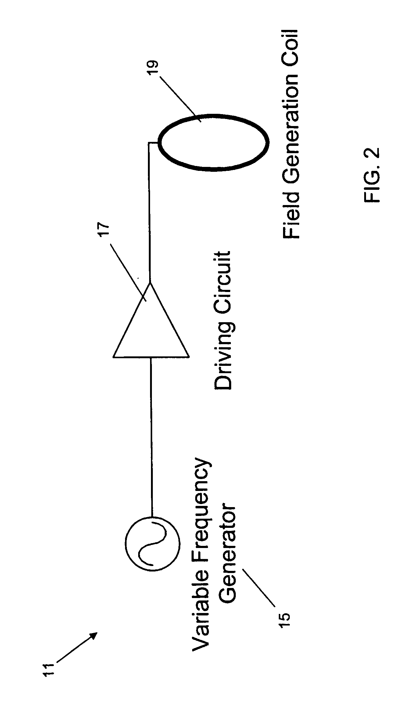
[0013] Preferably the radio frequency receiver is operable to selectively receive signals at a plurality of different frequencies. An advantage of having a variable frequency transmitter is that it provides a means of avoiding interference from man made noise, since such noise typically varies with time, frequency and location. Identification of a frequency selective sequence could be identified by the processing system arranged to evaluate correlation between processed signals.
[0014] Alternatively or additionally the radio frequency receiver is operable to identify a modulation pattern within a transmitted radio signal and compare the identified pattern with one or more predetermined modulation patterns. An advantage of configuring a proximity detecting equipment such that transmitted and received signals cooperate by means of a modulation signal is that the receiver can distinguish between valid transmissions and interfering signals such as man made noise.
[0016] Preferably the antenna circuit comprises a coil having a plurality of windings and tapping means for connection to said windings. The tapping means is arranged to vary the loss associated with the antenna circuit by connection to a set of the plurality of windings, thereby removing energy from the coil and reducing the Q factor of the coil. By reducing the Q factor of the antenna circuit the bandwidth thereof is increased, and this then enables the antenna circuit to transmit at the various frequencies.

Problems solved by technology

In addition, received signals can destructively interfere at the receiver, causing a problem known as fading.
Whilst these problems can be reduced by employing several or more receivers, this increases the complexity and cost.
Essentially, therefore, in order to provide accurate measurements of location at reasonable cost, high frequency systems require a clear line-of-sight between the antennas of the transmitter and receiver, which is difficult to achieve for most ground-based location determining systems.
In order to measure time accurately, the resolution of the pulse has to be fine, which means that such systems use high frequencies, and are subject to the reflection and absorption problems described above, so that the time of arrival can be the “time of arrival after experiencing several reflections” and thus highly inaccurate.
Since this method is wholly dependent on signal strength, it is particularly sensitive to fading (where the signals received destructively interfere with one another) and can, on occasion, yield no signal strength whatsoever.

Method used


Image

  • Proximity detecting apparatus
  • Proximity detecting apparatus
  • Proximity detecting apparatus

Examples


Embodiment Construction

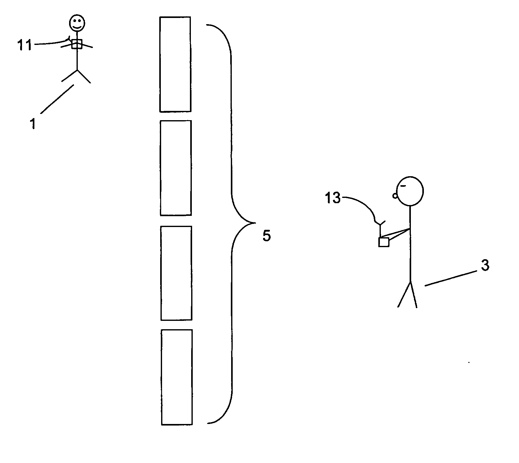
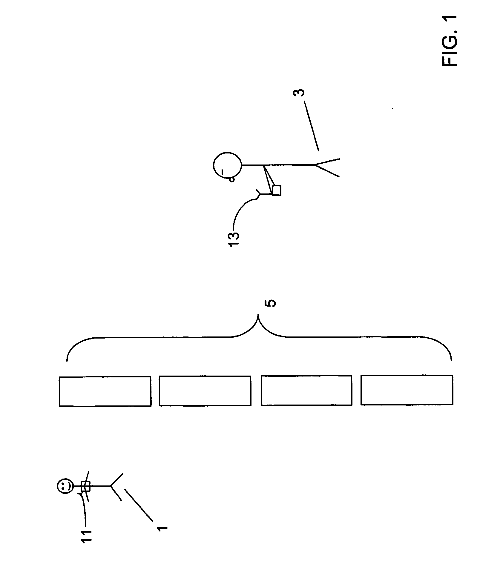
[0029] Embodiments of proximity detecting apparatus according to the invention will now be described for an example scenario in which the degree of proximity between a child and a guardian is monitored by equipment associated with the guardian. Referring to FIG. 1, the child 1 and guardian 3 are located in a crowded area comprising obstacles, several doorways and passageways (shown collectively as part 5 in FIG. 1). The child 1 is equipped with a radio frequency (RF) transmitter 11 and the guardian is holding a radio frequency (RF) receiver 13. The components and operation of the RF transmitter and RF receiver 11, 13 will be described in detail below, but in overview, the RF transmitter 11 transmits low frequency signals either constantly or in response to an external input. The signals so transmitted are received by the RF receiver 13, which comprises one or more antenna coils and measures the output from each coil, then amplifies, mixes to an intermediate frequency for filtering a...


PUM


Abstract

Arrangements according to the invention embody a radio frequency receiver for use in a proximity detecting system, the radio frequency receiver comprising at least one antenna coil operable to receive radio frequency signals; tunable receiver circuitry arranged in operative association with the antenna coil and being arranged to modify the frequency at which radio signals are received by the radio frequency receiver; and a signal processor arranged to amplify and filter signals received by the radio frequency receiver, wherein the radio frequency receiver is operable to receive and process radio signals of frequencies between 100 kHz and 10 MHz. By operating in the low frequency range, multi-path problems associated with high frequency equipment (such as reflections from objects located between the path of the transmitter and receiver) are significantly reduced, whilst distance between transmitter and receiver can be identified extremely accurately.

Description

FIELD OF THE INVENTION [0001] The present invention relates to proximity detecting apparatus and is concerned particularly with radio frequency proximity detecting apparatus that operate in the low radio frequency range. The present invention also relates to radio frequency transmitter and radio frequency receiver designs generally. BACKGROUND OF THE INVENTION [0002] Identifying the relative or absolute location of an object has always been of interest, and historically it has been an almost essential part of survival. As a result, development of technical means for identifying location has always had momentum. More recently location based services (which deliver content based on a location) have become increasingly popular, so that location is now used in leisure applications as well as the traditional applications of security and survival. [0003] There is a myriad of methods for identifying the location of an object and corresponding means for performing those methods, and these c...

Claims


Application Information

Patent Timeline
IPC IPC(8): G01S13/08H04B7/24G08B1/08G01S11/06H04B5/00H04B7/08
CPCG01S11/06H04B7/0822H04B5/0081
Inventor RICHARDS, TONYFITZ, STEVE
Owner PLEXTEK LIMITED
Learn More