

Antenna apparatus and radio communication apparatus
- Summary
- Abstract
- Description
- Claims
- Application Information
AI Technical Summary
Benefits of technology
Problems solved by technology
Method used
Image

Examples
first embodiment
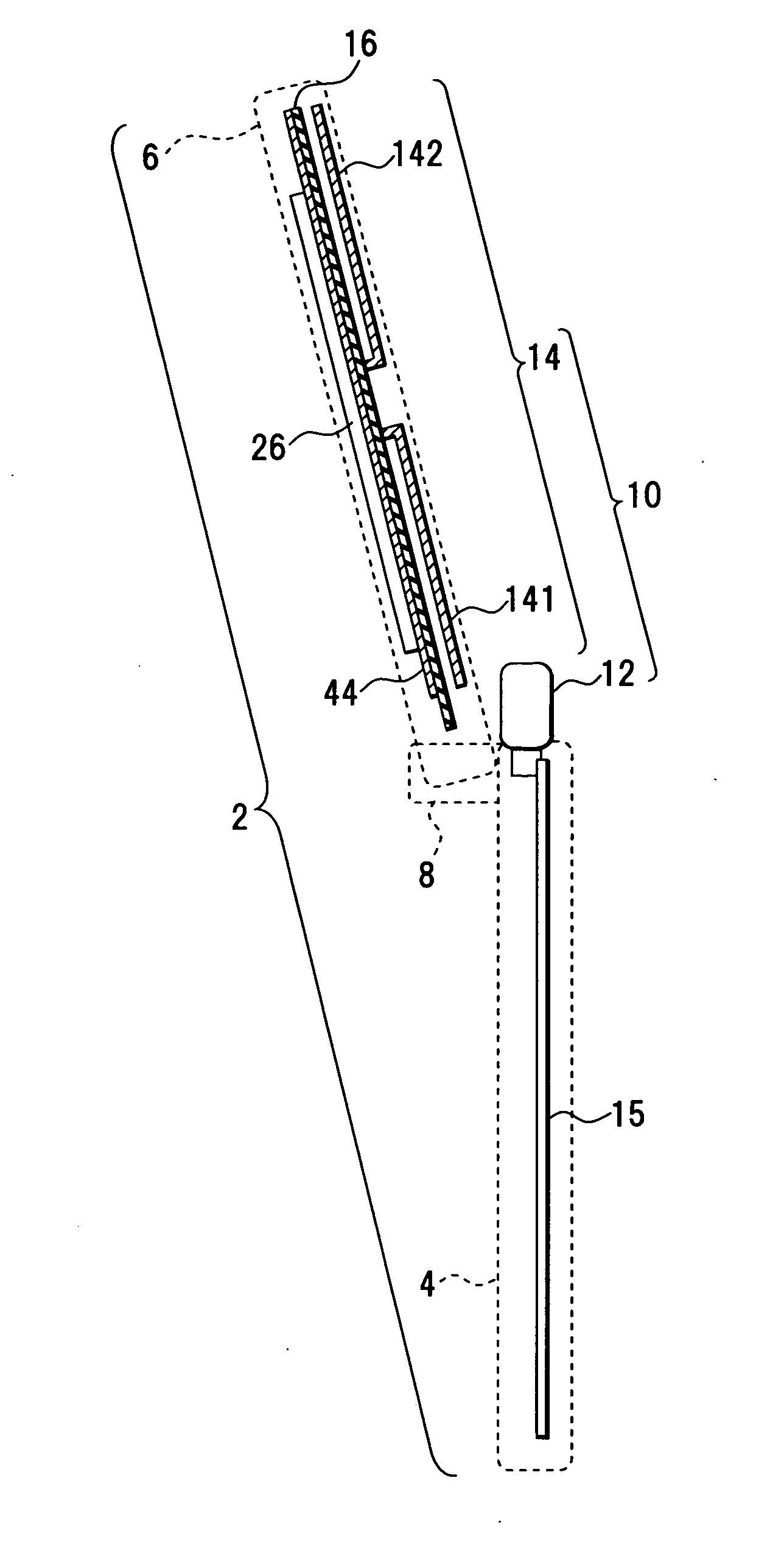
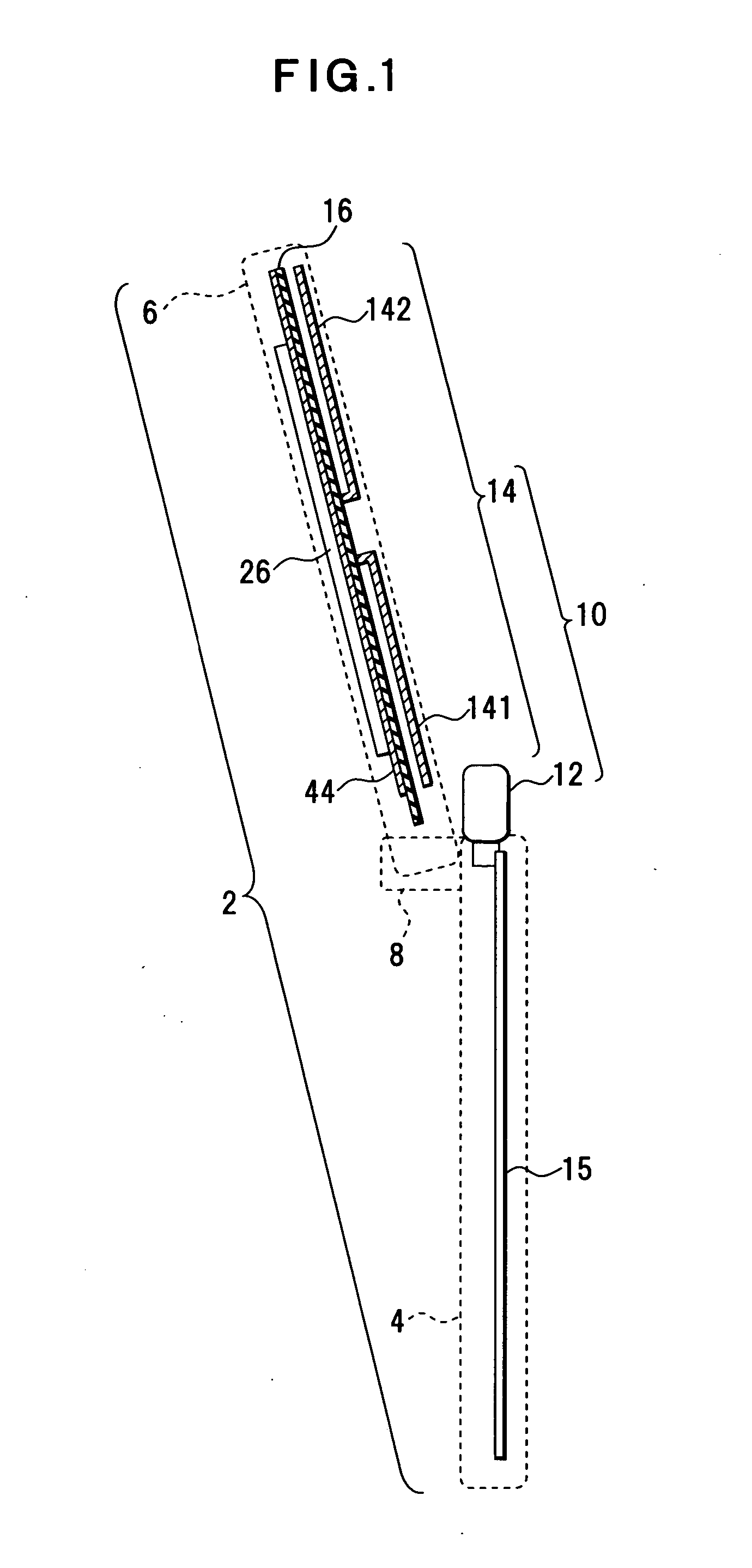
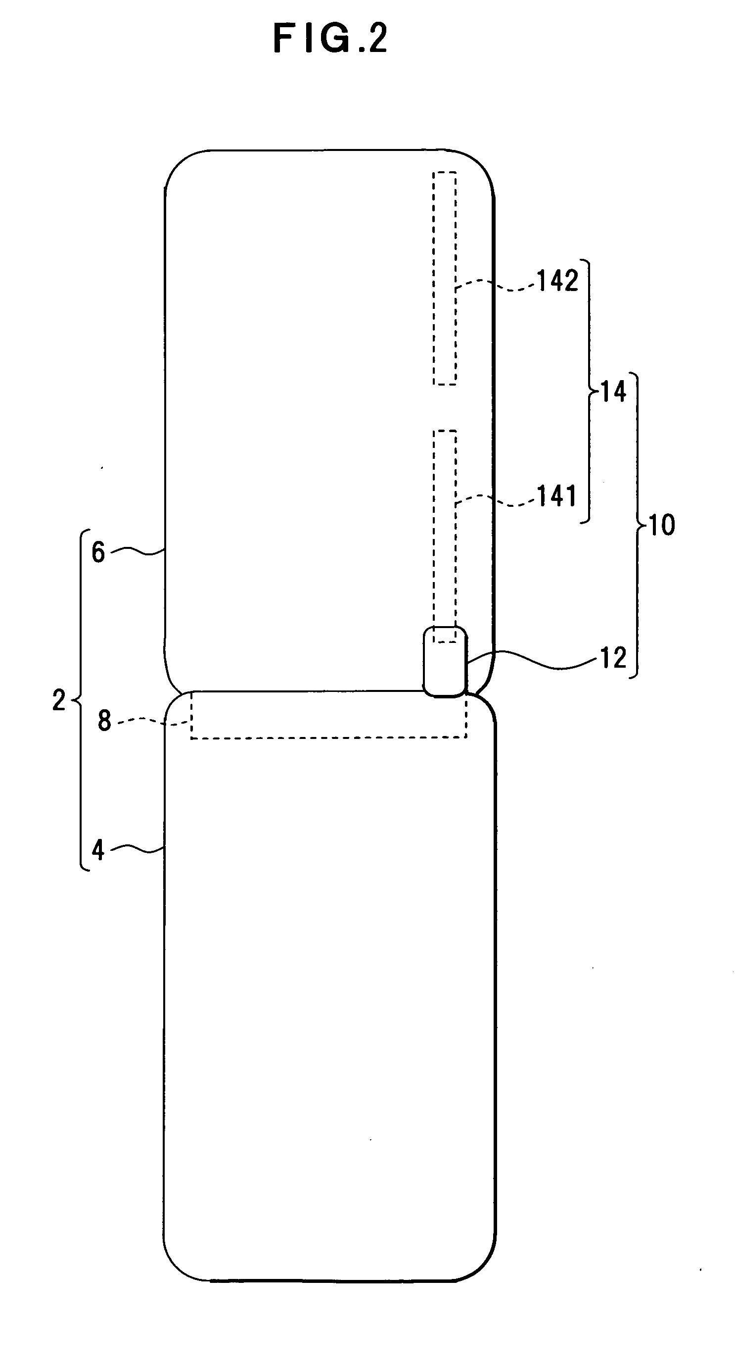
[0049] A first embodiment of the present invention will be described with reference to FIGS. 1, 2, 3, and 4. FIG. 1 is a cross-section diagram of an antenna apparatus portion of a cellular phone; FIG. 2 shows a rear side of the cellular phone; FIG. 3 shows a configuration example of the antenna apparatus of the cellular phone; and FIG. 4 shows a front side of the cellular phone.
[0050] A cellular phone 2 is an example of a radio communication apparatus using a plurality of radio communication frequencies and, in the cellular phone 2 of this embodiment, a first casing unit 4 and a second casing unit 6 are coupled by a hinge unit 8 such that the casing units 4, 6 can be opened and closed. Each casing unit 4, 6 may be made of a conducting material such as metal or may be made of an insulating material such as synthetic resin.
[0051] The cellular phone 2 is provided with an antenna apparatus 10 for multiband, and the antenna apparatus 10 includes a main antenna 12 that is a feeding elem...
second embodiment
[0063] A second embodiment of the present invention will be described with reference to FIGS. 9, 10, 11A, and 11B. FIG. 9 is a cross-section diagram of a configuration example of an antenna apparatus and a cellular phone including a passive element in a casing unit; FIG. 10 shows a configuration example of the cellular phone; and FIGS. 11A and 11B show connection between the passive element and a circuit substrate. In FIGS. 9 to 11B, the same numerals are added to the same portions as FIGS. 1 to 8.
[0064] In this cellular phone 2, the elements 141, 142 of the passive element 14 are disposed within the rear side of the casing unit 6, and the casing unit 6 is provided with elastic contacts 46, 48 connected to the opposite ends of the elements 141, 142. The circuit substrate 16 is disposed in the casing unit 6 and is provided with contact portions 50, 52 corresponding to the elastic contacts 46, 48.
[0065] As shown in FIG. 10, the PIN diode 18 is disposed between the contact portions 5...
third embodiment
[0069] A Third embodiment of the present invention will be described with reference to FIGS. 12 and 13. FIG. 12 shows a mounting form of a passive element of a cellular phone and FIG. 13 is a cross-section diagram of a passive element portion. In FIGS. 12 and 13, the same numerals are added to the same portions as FIGS. 1 to 11B.
[0070] In this embodiment, each element 141, 142 of the antenna apparatus 10 is constituted by a conductor pattern formed on the circuit substrate 16. An antenna region 54 and a ground conductor region 56 are set on the circuit substrate 16; in the antenna region 54, an insulating plate is exposed on the surface of the circuit substrate 16; and in the ground conductor region 56, a ground conductor 58 is formed on the insulating plate. The conductive patterns of the elements 141, 142 are formed on the antenna region 54. Therefore, in the antenna apparatus 10, as shown in FIG. 13, an insulating space d is established between the element 141, 142 disposed on t...
PUM
 Abstract
Description
Claims
Application Information