Turbidity sensor

a technology of turbidity sensor and turbidity measurement, which is applied in the direction of cleaning equipment, tableware washing/rinsing machine details, instruments, etc., can solve the problems of complex production process, high production cost, and inability to accurately produce lenses, etc., to achieve precise transmission measurement and production in a simple and economical manner

Inactive Publication Date: 2007-08-16
EMZ HANAUER
View PDF14 Cites 7 Cited by
  • Summary
  • Abstract
  • Description
  • Claims
  • Application Information

AI Technical Summary

Benefits of technology

[0008] The object of the invention is to provide a sensor to detect the transmission of a fluid used in a washing machine or dishwasher, which can be produced in a simple and economic manner, in particular requires no selected transmitter and receiver and allows a precise transmission measurement.

Problems solved by technology

The transmitters required are however expensive.
In view of the small dimensions of such sensors, the use of lenses requires precisely produced lenses and costly production processes to arrange the lenses correctly.
This procedure complicates the production process in particular when the transmitter and receiver are to be connected on a circuit board using SMD technology.

Method used


Image

  • Turbidity sensor
  • Turbidity sensor
  • Turbidity sensor

Examples


Embodiment Construction

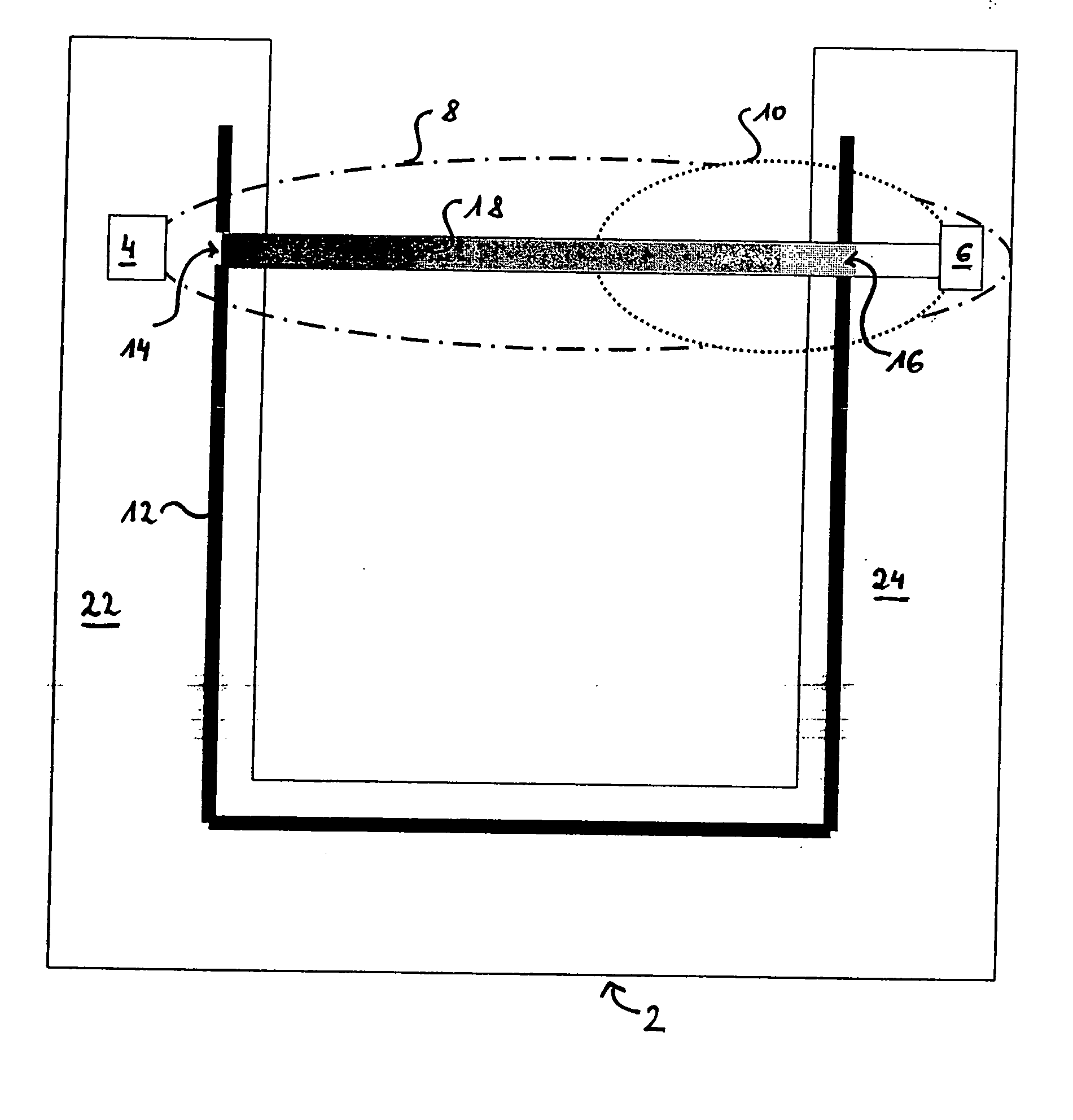
[0055] The simplified view of a sensor according to the invention in FIG. 1 shows a carrier 2 on which are attached a transmitter 4 and a receiver 6. As a carrier 2 is preferably provided a circuit board designed for SMD technology. As transmitter 4 and receiver 6 are provided optical components to provide an optical measurement section. For example as a transmitter 4 an LED can be used while as a receiver 6 a photo transistor, a photo diode or a solar cell can be used.

[0056] The transmitter 4 has an emission characteristic indicated by the dashed outline 8. The receiver 6 has a reception characteristic indicated by the dashed outline 10. The emission characteristic 8 and reception characteristic 10 show for the sake of simplicity only the transmitter and receiver main lobes of the transmitter 4 and receiver 6; secondary lobes of both the transmitter 4 and receiver 6 are not shown.

[0057] Also arranged on the carrier 2 is a diaphragm system 12 which is spaced both from the transmit...


PUM

PropertyMeasurementUnit
aperture angleaaaaaaaaaa
lengthsaaaaaaaaaa
transmissionaaaaaaaaaa

Abstract

Sensor for transmission measurement in a washing machine or dishwasher, with a carrier (2) a transmitter (4) attached to the carrier (2) to emit a transmitter beam, a receiver (6) attached to the carrier (2) to receive the beam generated by the transmitter (4), and a diaphragm system arranged on the carrier spaced from the transmitter and/or receiver.

Description

AREA OF THE INVENTION [0001] The present invention concerns a sensor to measure the transmission of a fluid used in a washing machine or dishwasher and a method for production of such a sensor. BACKGROUND OF THE INVENTION [0002] Sensors to detect the clouding of a fluid used in a washing machine or dishwasher are well known. Such sensors comprise a transmitter which emits a measurement beam through a fluid, the transmission of which is to be determined, and a receiver in order to receive the beam based on the measurement beam after passage through the fluid. Comparison of the measurement beam emitted by the transmitter and the beam received by the receiver allows determination of the fluid transmission. [0003] The transmission determined by means of such a sensor may deviate from the actual fluid transmission for several reasons. On its propagation path through the fluid the measurement beam from the transmitter is subject to scatter. Scattered parts of the measurement beam however ...

Claims


Application Information

Patent Timeline
Patent Type & Authority Applications(United States)
IPC IPC(8): G01N21/00A47L15/42D06F34/22G01N21/53
CPCA47L15/4297G01N21/534D06F39/004D06F34/22
Inventor SCHENKL, JOHANN
Owner EMZ HANAUER
Why Eureka
Try Eureka