Printing device

a printing device and image technology, applied in the field of printing devices, can solve the problems of long time to complete, difficult use of retrieving a desired image from among the large number of stored images, and difficult to retrieve a desired image from among the large number of stored images, and achieve the effect of easy process

Active Publication Date: 2007-08-16
138 EAST LCD ADVANCEMENTS LTD
View PDF3 Cites 12 Cited by
  • Summary
  • Abstract
  • Description
  • Claims
  • Application Information

AI Technical Summary

Benefits of technology

[0012]An object of the present invention is to provide a technology affording an easy process for selecting and printing only a desired image from among a plurality of images.

Problems solved by technology

Since such high-capacity memory cards can store large numbers of images, it is sometimes difficult for the use to retrieve a desired image from among the large number of stored images.
Consequently, the user will have to select a desired image worth printing from among this large number of similar images, which is extremely laborious.
Since the determination as to whether a human subject appears is accomplished through analyzing the image data of each individual image, it takes a relatively long time to complete the determination process for all of the images, and a resultant problem is that it takes a relatively long time for printing of a preferred image (an image in which a human subject appears) to be completed.

Method used


Image

  • Printing device
  • Printing device
  • Printing device

Examples


embodiment 1

A. EMBODIMENT 1

A1. General Configuration of Printer

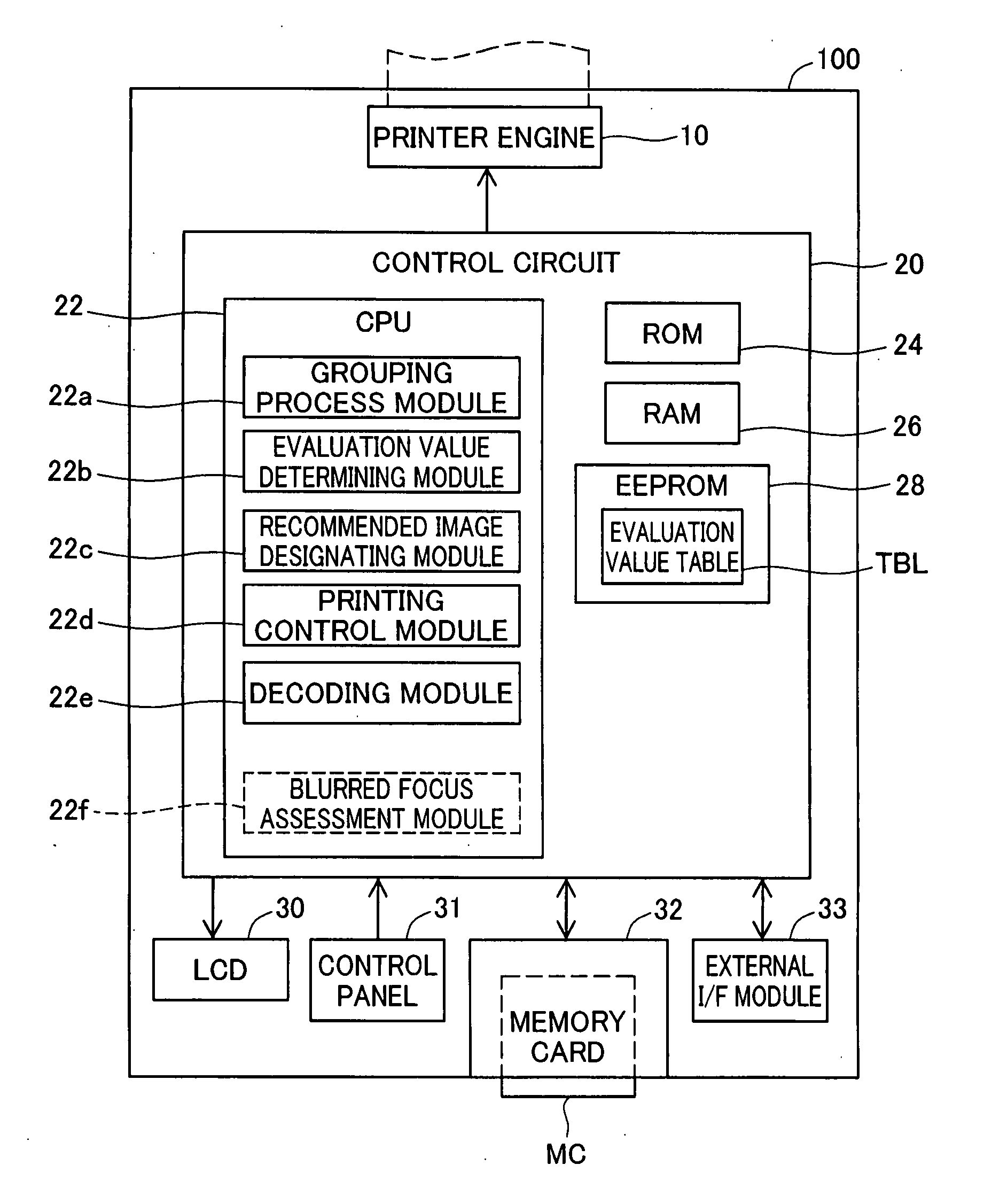
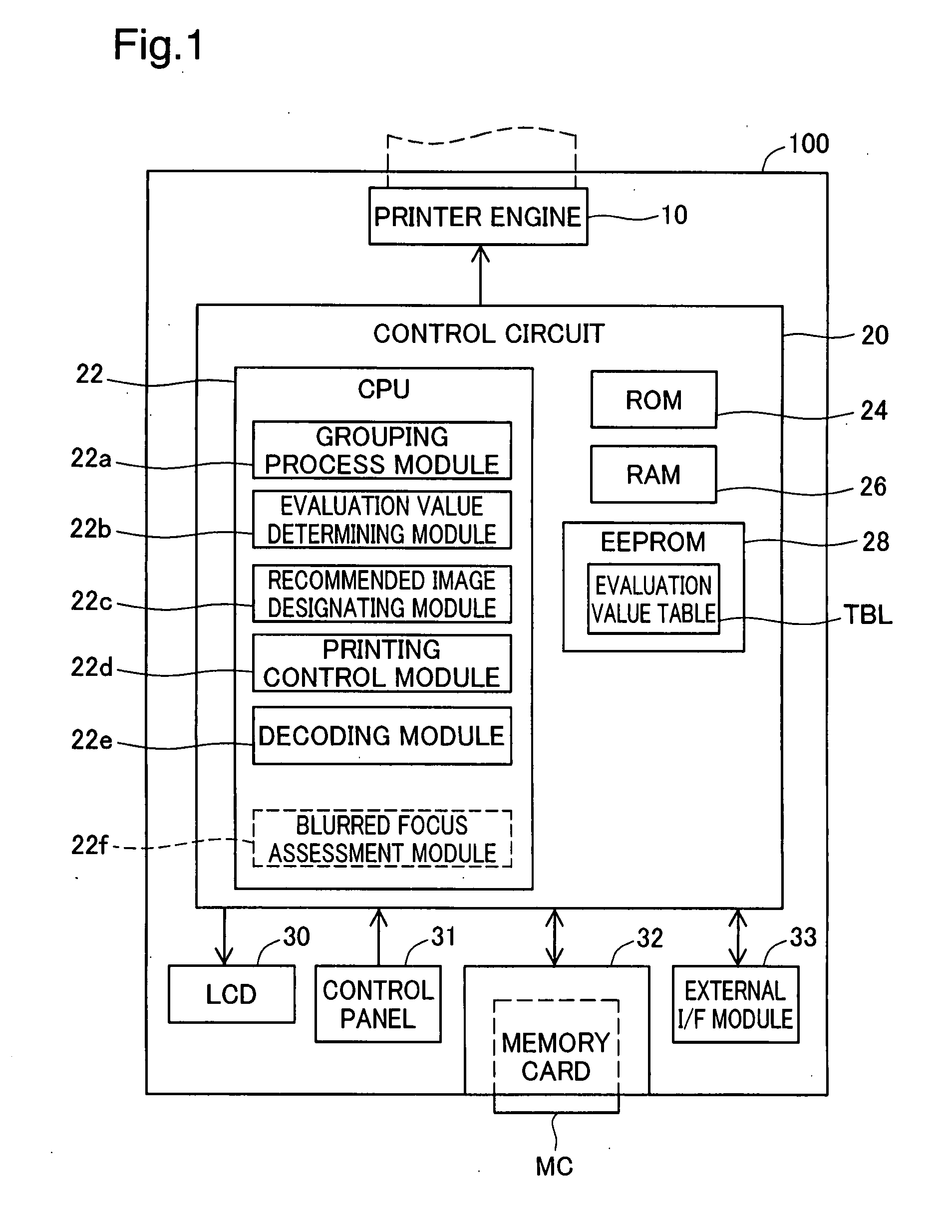
[0034]FIG. 1 is an illustration of the general configuration of a printer as a first embodiment of the present invention. The printer 100 is equipped with a control circuit 20; a printer engine 10 connected to the control circuit 20; a liquid crystal display 30; a control panel 31; a memory card slot 32; and an external interface 33.

[0035]The printer engine 10 is furnished with a carriage (not shown) having ink cartridges, not shown, installed thereon, and a motor for driving the carriage (not shown). The printer engine 10 is the functional portion that actually executes printing. The liquid crystal display 30 is a functional portion for displaying menus of various kinds. The control panel 31 is furnished with control buttons (not shown) allowing the user to make various settings. The memory card slot 32 is a functional portion for reading data from an inserted memory card. The external interface 33 is an interface for connecting a...

embodiment 2

B. EMBODIMENT 2

[0068]In Embodiment 1 discussed previously, designation of the recommended image within a group is made on the basis of an evaluation value indicating the quality of composition. However, this leaves a risk of selecting as the recommended image a flawed image that, while having good composition, has blurred focus. Therefore, in the present embodiment, a blurred focus assessment process, to be discussed later, is carried out to designate images free from blurred focus as the recommended images. Additionally, the grouping process is accelerated by utilizing thumbnail images for executing the process.

[0069]FIG. 6 is a flowchart depicting the procedure of the recommended image printing process in Embodiment 2. The procedure of FIG. 6 is the same as the procedure of FIG. 3 except that the content of Steps S202-226 of FIG. 3 has been modified, and Steps S300, S350, S352, and S354 have been added between Step S226 and Step S228. Steps S202a-224a of FIG. 6 differ from Steps S...

embodiment 3

C. EMBODIMENT 3

[0076]FIG. 7 is a flowchart depicting the recommended image printing process of Embodiment 3. The procedure of FIG. 7 is the same as the procedure of FIG. 3 except that Step S502 has been added between Step S218 and Step S220.

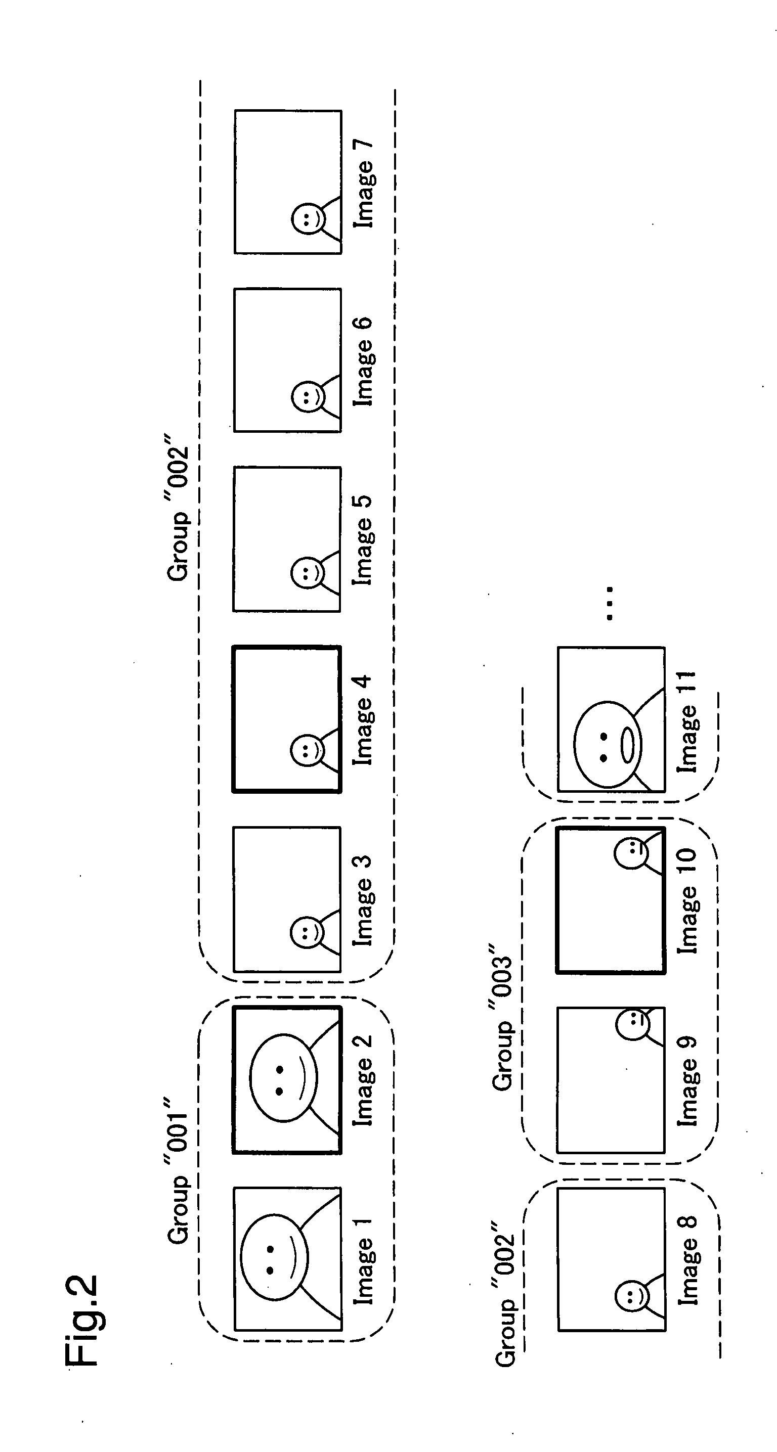
[0077]In Step S218, in the event that an image selected for processing is determined to be similar to the immediately preceding image, unlike Embodiment 1, the grouping process module 22a will then further determine whether the number N of images belonging to the immediately preceding group is less than a threshold value Na, where N is an integer equal to or greater than 2. Here, the “number N of images belonging to the immediately preceding group” is not considered to include the image currently selected for processing, and refers to the number of images assigned to the immediately preceding group up to that point in time. In the present embodiment, the threshold value Na is assumed to be “5,” but could be set to any integer equal to or greater ...


PUM


Abstract

A printing device comprises an evaluation value determining module, a grouping process module, a recommended image designating module, and a printing process module. The evaluation value determining module determines, for each image, a first evaluation value for a prescribed evaluation item. The grouping process module performs a sorting process to sort the plurality of images into groups of similar images. The recommended image designating module designates, for each group, a recommended image from among the images belonging to the group, based on the first evaluation value. The printing process module prints the designated recommended image.

Description

CROSS REFERENCE TO RELATED APPLICATIONS[0001]The present application claims the priority based on Japanese Patent Application No. 2006-29319 filed on Feb. 7, 2006, the disclosure of which is hereby incorporated by reference in its entirety.BACKGROUND OF THE INVENTION[0002]1. Field of the Invention[0003]The present invention relates to a technology for classifying a plurality of images into groups of similar images, and for printing a recommended image of each group.[0004]2. Description of the Related Art[0005]In recent years, high-capacity memory cards have become widespread as memory media for digital cameras and mobile phones. Since such high-capacity memory cards can store large numbers of images, it is sometimes difficult for the use to retrieve a desired image from among the large number of stored images. Accordingly, there has been proposed a printing device able to extract and print an image desired by the user, from among a large number images stored on a memory card (see JP...

Claims


Application Information

Patent Timeline
Patent Type & Authority Applications(United States)
IPC IPC(8): G06F3/12
CPCG06K9/00228G06T7/0004G06T2207/30144H04N2201/0087H04N1/00175H04N1/00188H04N1/00278H04N1/00132G06V40/161
Inventor AISO, SEIJI
Owner 138 EAST LCD ADVANCEMENTS LTD
Why Eureka
Try Eureka