Illuminating device for imaging apparatus

Inactive Publication Date: 2007-08-16
SONY CORP
View PDF2 Cites 0 Cited by
  • Summary
  • Abstract
  • Description
  • Claims
  • Application Information

AI Technical Summary

Benefits of technology

[0013] According to an embodiment of the present invention, since the detection switches that turn on/off the supply of the detection voltages from the respective voltage detecting units to the voltage monitoring unit are provided with respect to each battery, the generation of

Problems solved by technology

By the way, when current is allowed to flow in a condition in which the output voltage thereof is equal to or less than a pre

Method used


Image

  • Illuminating device for imaging apparatus
  • Illuminating device for imaging apparatus
  • Illuminating device for imaging apparatus

Examples


Example

[0018] Next, the first embodiment of the present invention will be described with reference to the drawings.

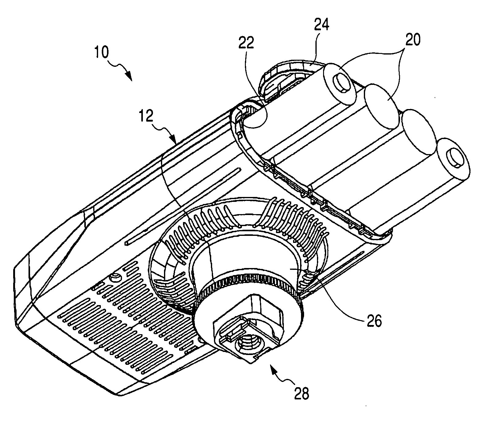
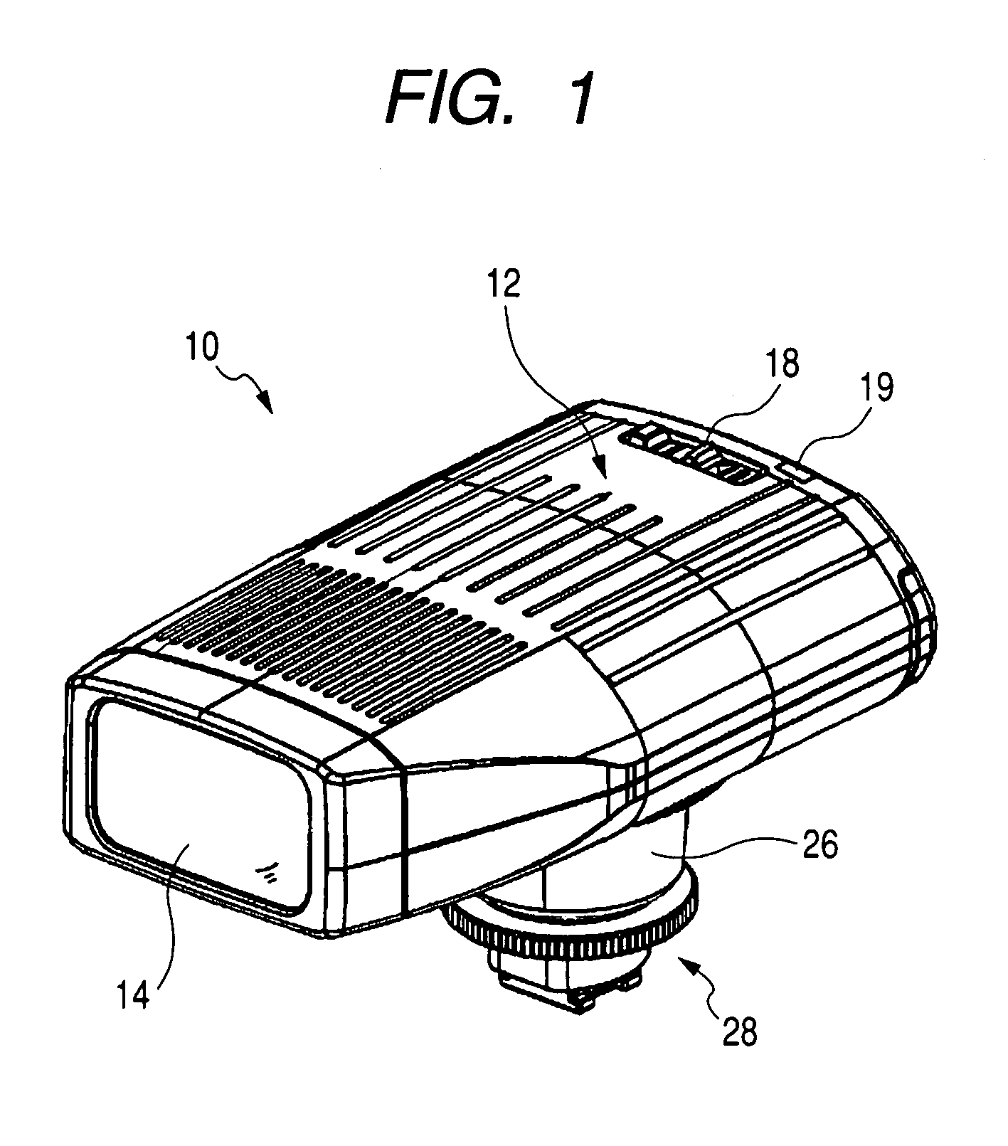
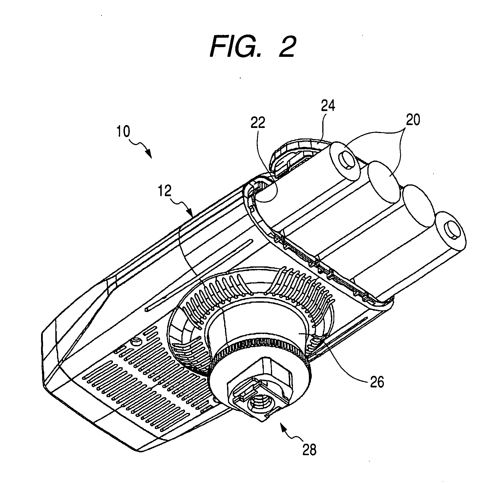
[0019]FIGS. 1 and 2 are perspective views of an illuminating device 10 according to the first embodiment, and FIG. 3 is a circuit diagram showing a constitution of a control system of the illuminating device 10.

[0020] As shown in FIGS. 1 and 2, the illuminating device 10 is a video light mounted on an imaging apparatus such as a video camera to irradiate a subject with light, and configured to operate without power supply from the imaging apparatus.

[0021] The illuminating device 10 has a case 12 forming an exterior thereof, and the case 12 has an anteroposterior length, a horizontal width shorter than the length, and a vertical height shorter than the width.

[0022] An opening is provided on the front end of the case 12, a transparent plate 14 is fitted in the opening, and a light source 16 (see FIG. 3) of an electric bulb is located facing the transparent plate 14 within th...


PUM


Abstract

An illuminating device for imaging apparatus includes: a light source; plural batteries that supply power to the light source; plural detection voltage generating units that are provided with respect to each battery and generate detection voltages from output voltages of the batteries; a voltage monitoring unit that is supplied with the plural detection voltages, respectively, and determines whether the output voltages of the batteries are equal to or less than a predetermined specified value or not with respect to each battery; and a control unit that turns on/off the supply of the power to the light source based on a determination result of the voltage monitoring unit, wherein detection switches that turn on/off the supply of the detection voltages from the respective detection voltage generating units to the voltage monitoring unit based on the control by the control unit are provided with respect to each battery.

Description

CROSS REFERENCES TO RELATED APPLICATIONS [0001] The present invention contains subject matter related to Japanese Patent Application JP 2006-034910 filed in the Japanese Patent Office on Feb. 13, 2006, the entire contents of which being incorporated herein by reference. BACKGROUND OF THE INVENTION [0002] 1. Field of the Invention [0003] The present invention relates to an illuminating device for imaging apparatus. [0004] 2. Background Art [0005] There are illuminating devices such as a video light mounted on an imaging apparatus such as a video camera for irradiating a subject with imaging auxiliary light (see JP-A-11-237661 (patent document 1)). [0006] As such an illuminating device, there is provided an illuminating device that operates without power supply from the imaging apparatus but with a battery mounted in the device itself as power supply independent from the electronic equipment. [0007] By the way, when current is allowed to flow in a condition in which the output voltage...

Claims


Application Information

Patent Timeline
IPC IPC(8): F21V7/04G05D25/00
CPCH04N5/2256Y02B20/144H05B39/047Y02B20/00H04N23/56G03B15/02H04N23/00
Inventor CHIHARA, EIJI
Owner SONY CORP
Why Eureka
Try Eureka