Seal tape, light modulating element, light modulating structure and method for producing light modulating structure

A technology of dimming components and sealing tapes, applied in optics, shading screens, nonlinear optics, etc., can solve problems such as liquid crystal layer degradation and liquid crystal layer infringement, and achieve the effects of improving workability, preventing damage, and preventing degradation

Active Publication Date: 2013-01-02
SEIKO ELECTRIC
View PDF10 Cites 4 Cited by
  • Summary
  • Abstract
  • Description
  • Claims
  • Application Information

AI Technical Summary

Problems solved by technology

[0007] Although the liquid crystal film that does not use a sealing material can prevent the intrusion of air or moisture from the outside of the dimming window by the intermediate film, because the liquid crystal layer of the liquid crystal film is in direct contact wi

Method used


Image

  • Seal tape, light modulating element, light modulating structure and method for producing light modulating structure
  • Seal tape, light modulating element, light modulating structure and method for producing light modulating structure
  • Seal tape, light modulating element, light modulating structure and method for producing light modulating structure

Examples


no. 1 approach )

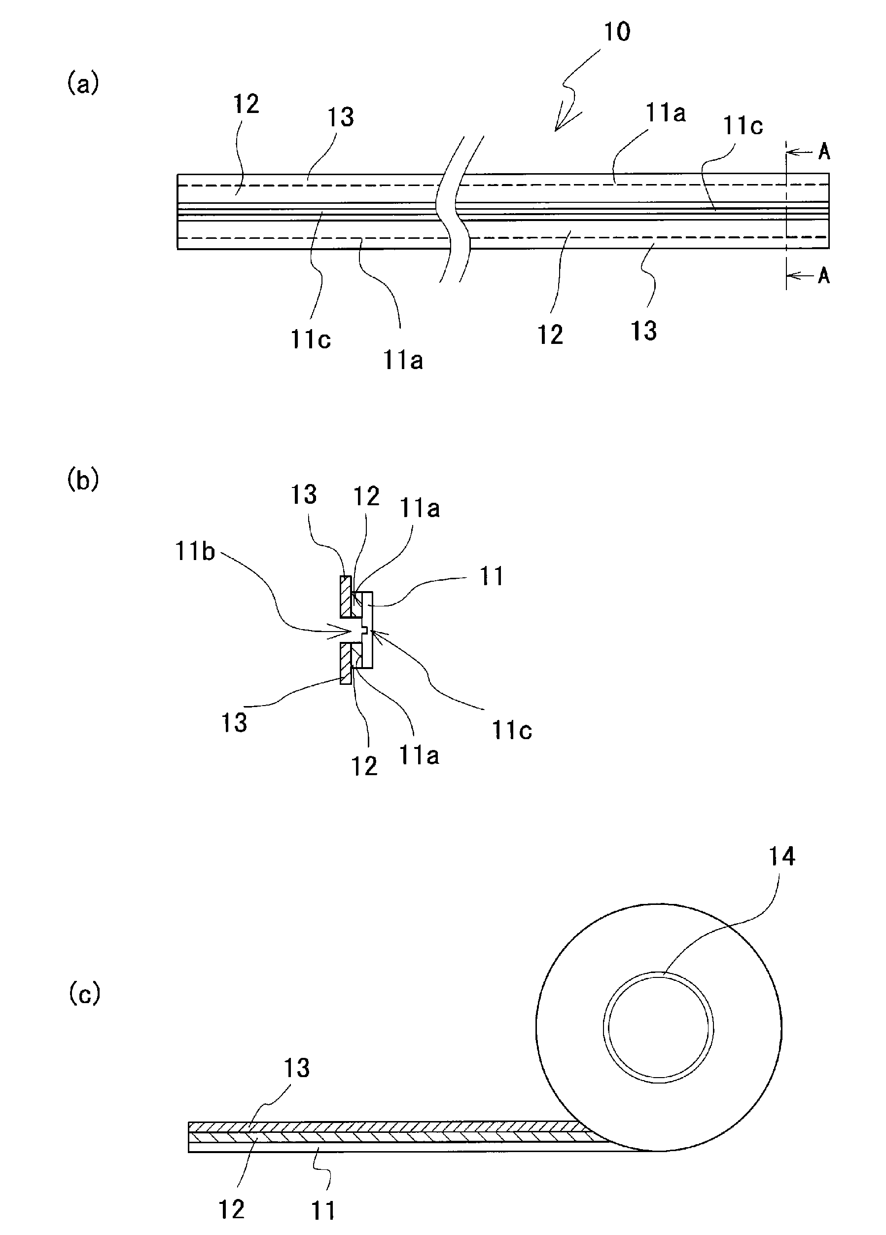
[0046] Such as figure 1 As shown, the sealing tape 10 includes: a strip-shaped base material 11; an adhesive portion 12 formed by disposing an adhesive on both edge portions 11a in the longitudinal direction of the base material 11; The area between the two edge portions 11a of the base material 11 is exposed along the length direction of the base material 11;

[0047] The base material 11 is a film with transparency, insulation, flexibility, toughness, heat resistance, cold resistance or chemical corrosion resistance, such as a polyester film, especially polyethylene terephthalate : PET) film. In addition, the base material 11 which concerns on this embodiment uses "Lumira (registered trademark)" manufactured by Toray Co., Ltd. with a width of 6 mm.

[0048] Adhesive portion 12 may be formed by directly applying an adhesive to base material 11 and drying the applied adhesive, or may be formed by affixing one side of the base material 11 with a double-sided adhesive tape. I...

no. 2 approach )

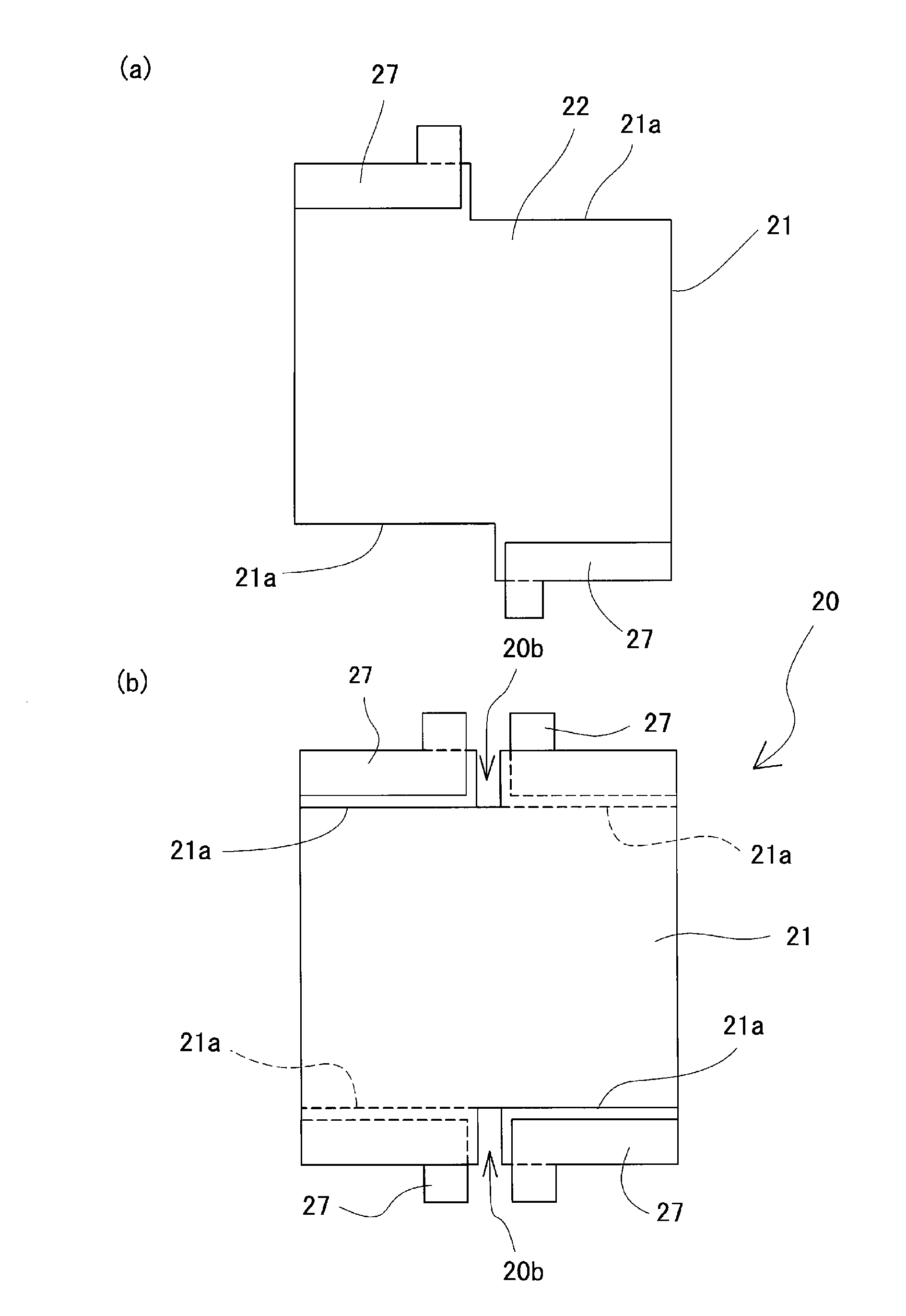
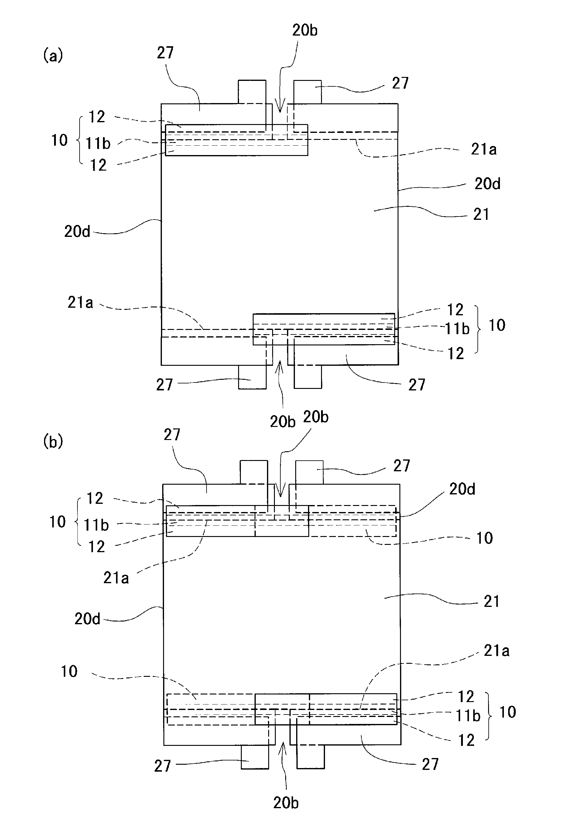
[0099] Figure 7 (a) is a plan view of an insulating substrate provided with a transparent electrode and an extraction electrode, Figure 7 (b) is used to illustrate Figure 7 (a) is a perspective view of opposing surfaces of two insulating substrates. Figure 8 (a) is a plan view showing a schematic configuration of the light control element according to the second embodiment, Figure 8 (b) is from Figure 8 (a) A side view of the four sides of the dimming element as viewed from the side where terminals protrude. Figure 9 (a) is at Figure 8 (a) The top view of the dimming element with the sealing tape attached to the half-cut line on the surface side of the dimming element, Figure 9 (b) is at Figure 9 (a) is a plan view of a light-adjusting element with a sealing tape attached to the half-cut line on the rear side of the light-adjusting element. Figure 10 (a) is at Figure 9 (b) A top view of the dimming element with the sealing tape 10 attached to the side where...

Embodiment 2

[0140] The dimming element 20 involved in Embodiment 2 is in Figure 13 In the plan view shown in (a), one side of the substantially rectangular insulating substrate 21 is cut so that the completely broken region 20 b is located in the substantially center of one of the four sides of the light-adjusting structure 100 , and the two cut insulating substrates are overlapped. The permanent substrate 21 is used to form a fully disconnected region 20b.


PUM

PropertyMeasurementUnit
Thicknessaaaaaaaaaa
Film thicknessaaaaaaaaaa
Thicknessaaaaaaaaaa

Abstract

Provided is a seal tape that can prevent deterioration of a light modulating layer by an intermediate film that includes a plasticizer and that can also improve workability during the production of a light modulating structure. The seal tape (10) comprises: a band-like base material (11); an adhesive section (12) formed by the provision of an adhesive on both edges (11a) in the longitudinal direction of the base material (11); an exposed section of base material (11b) that extends in the longitudinal direction of the base material (11) and is a region between both edges (11a) of the base material (11) located on the surface on which the adhesive section (12) is formed; and a releasing material (13) which covers the adhesive section (12) on both edges (11a) of the base material (11).

Description

technical field [0001] The present invention relates to a sealing tape that is arranged on the periphery of a pair of insulating substrates and seals a light-adjusting layer of a light-adjusting element, a light-adjusting element using the sealing tape, a light-adjusting structure, and a method for manufacturing a light-adjusting structure. The dimming element includes: a pair of substrates (hereinafter referred to as insulating substrates) at least one of which is transparent and insulating; transparent electrodes respectively arranged on the pair of insulating substrates; The lead-out electrodes electrically connected to the transparent electrodes exposed on the opposite surfaces of the insulating substrates; and the dimming layer sandwiched between a pair of insulating substrates. Background technique [0002] In recent years, dimming windows in which dimming elements such as liquid crystal films and dimming films are laminated on glass substrates have been used for windo...

Claims


Application Information

Patent Timeline
IPC IPC(8): G02F1/1333G02F1/1334G02F1/1339
CPCG02F1/1341E06B9/24G02F1/1339
Inventor 早田茂敏苣木雄一古川真悟斋藤洋平德永顺恒
Owner SEIKO ELECTRIC
Why Eureka
Try Eureka