

Air-conditioning device
A technology of air-conditioning device and throttling device, which is applied in the direction of reversible cycle compressor, lighting and heating equipment, machine operation mode, etc. It can solve the problem of not being able to cope with the mixed operation of cooling and heating, and achieve the effect of preventing deterioration
- Summary
- Abstract
- Description
- Claims
- Application Information
AI Technical Summary
Problems solved by technology
Method used
Image

Examples
Embodiment approach 1
[0034] figure 1 It is a schematic diagram showing an installation example of the air conditioner according to Embodiment 1 of the present invention. based on figure 1 An example of installation of an air conditioner will be described. In this air conditioner, each indoor unit can freely select a cooling mode or heating mode. In addition, contains figure 1 In addition, in the following drawings, the size relationship of each component may differ from actual ones.
[0035] exist figure 1 Among them, the air conditioner according to Embodiment 1 includes one outdoor unit 1 as a heat source unit, a plurality of indoor units 2 , and a heat medium relay unit 3 interposed between the outdoor unit 1 and the indoor units 2 . The heat medium converter 3 performs heat exchange between the heat source side refrigerant and the heat medium. The outdoor unit 1 and the heat medium relay unit 3 are connected by a refrigerant pipe 4 through which a heat source side refrigerant is conduct...
Embodiment approach 2
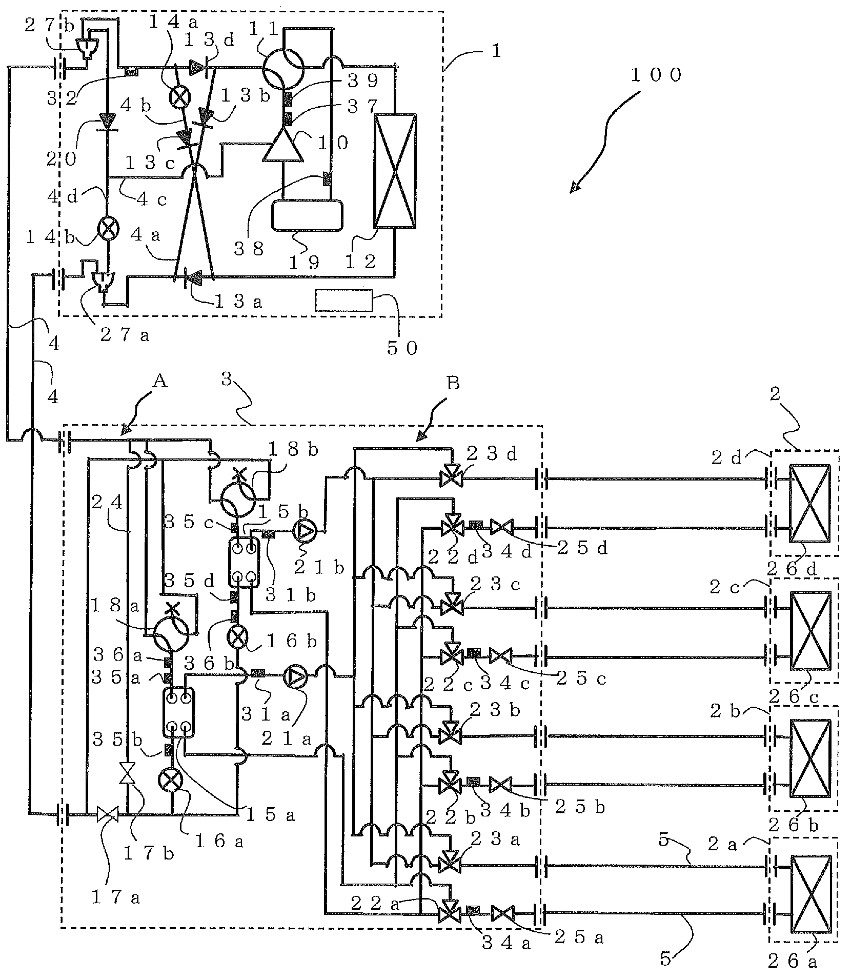
[0199] Figure 14 It is a figure which shows the structure of 100 A of air-conditioning apparatuses of Embodiment 2. In the air conditioner 100A according to Embodiment 2, the outdoor unit 1 includes an expansion device 14a, an expansion device 14b, and an expansion device 14c. That is, in Embodiment 1, the case of having the backflow prevention device 20 was described as an example, but in Embodiment 2, the throttle device 14a is moved to the position of the backflow prevention device 20 in Embodiment 1, and The throttle device 14c is provided at the position of the throttle device 14a in the first embodiment. The throttling device 14a and the throttling device 14b use a device that continuously changes the opening degree (opening area) such as an electronic expansion valve, and the throttling device 14c uses a capillary tube or a solenoid valve with a small opening area when opened. A device with a fixed opening area of the throttle, such as an on-off valve. The basic o...
Embodiment approach 3
[0207] In Embodiment 1 and Embodiment 2, the following system was described as an example, that is, the compressor 10, the first refrigerant flow switching device 11, the heat source side heat exchanger 12, the throttle device 14a, the throttle The device 14 b , the opening and closing device 17 , and the backflow prevention device 20 (the throttle device 14 c in Embodiment 2) are housed in the outdoor unit 1 . In addition, the use-side heat exchanger 26 is accommodated in the indoor unit 2 , and the heat exchanger related to heat medium 15 and the expansion device 16 are accommodated in the heat medium relay unit 3 . Furthermore, the outdoor unit 1 and the heat medium relay unit 3 are connected by a set of two pipes, and the heat source side refrigerant is circulated between the outdoor unit 1 and the heat medium relay unit 3 and passed through the two sets of pipes respectively. Connect between the indoor unit 2 and the heat medium converter 3, circulate the heat medium betw...
PUM
 Abstract
Description
Claims
Application Information