
Method for controlling handoff in optical distributed network system using multi input multi output

a distributed network and handoff technology, applied in multiplex communication, orthogonal multiplex, wireless commuication services, etc., can solve the problems of limited cell construction and management, difficult to overcome an essential latency time, etc., to minimize latency time and uniform data transmission

Active Publication Date: 2007-08-16
SAMSUNG ELECTRONICS CO LTD
View PDF4 Cites 33 Cited by
  • Summary
  • Abstract
  • Description
  • Claims
  • Application Information

AI Technical Summary

Benefits of technology

[0033]The present invention provides a method for controlling a handoff in an optical distributed network system using multi-input multi-output frequently implemented between picocells for a B3G or 4th generation mobile communication system, and thus minimizing a latency time and making uniform data transmission possible.

Problems solved by technology

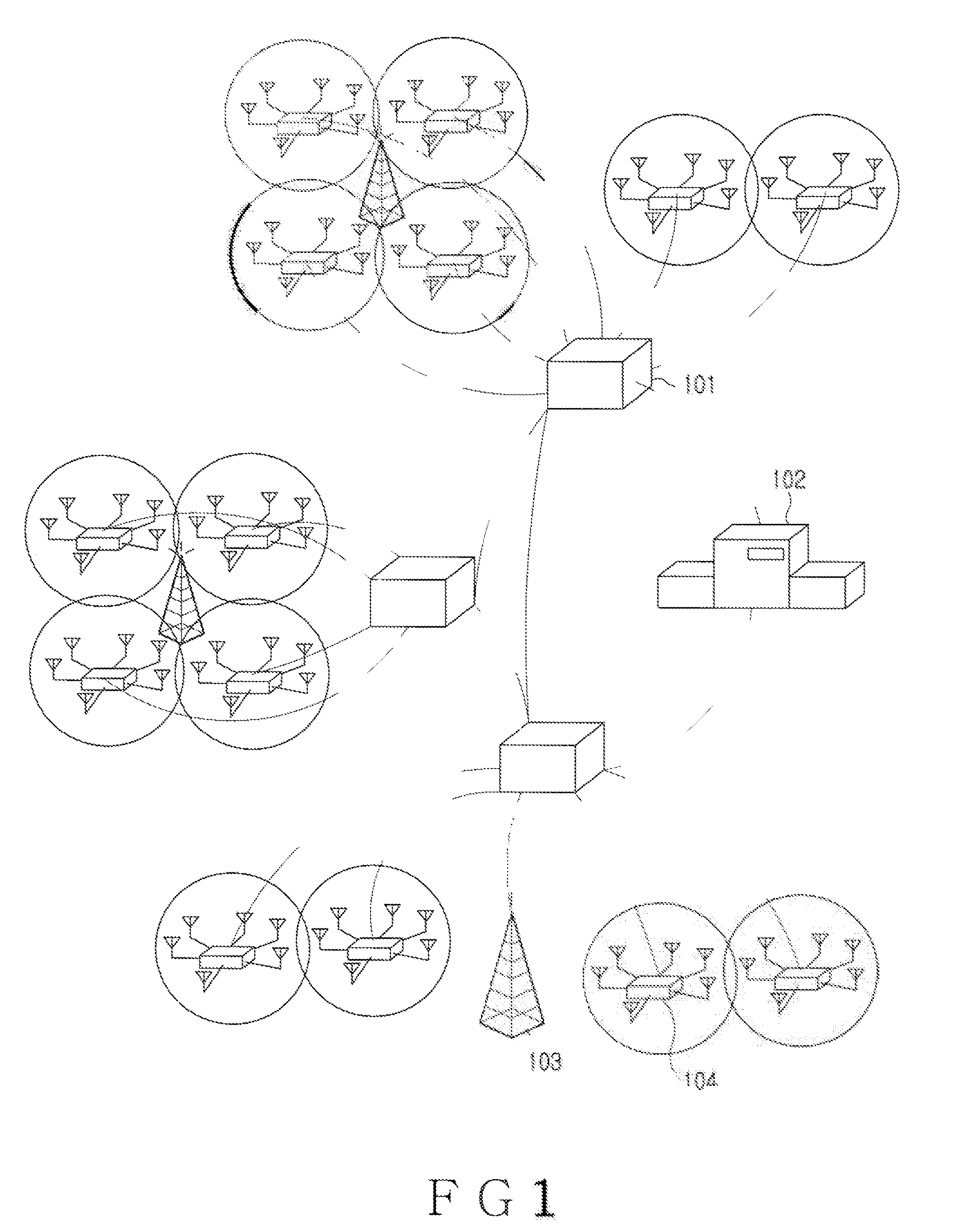
However, the multi hop technology has a drawback in that frequency interference occurs and thus, is limited in constructing and managing the cell.
The most important issue of the distributed network system constructed by the many picocells is to process a handoff that is frequently implemented when the mobile terminal moves between the picocells so as to keep a state of uninterrupted communication.
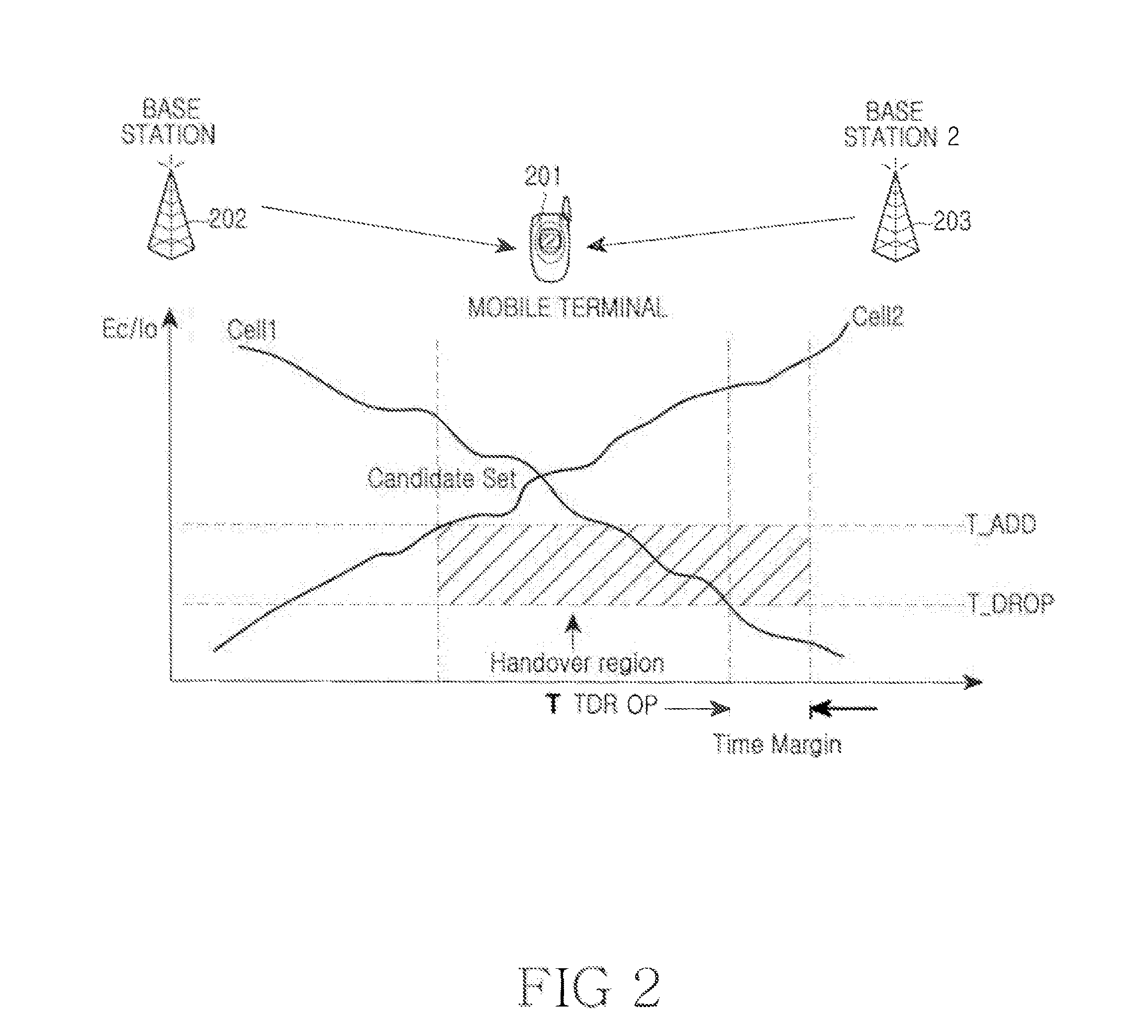
However, the conventional soft handoff in the mobile communication system has a drawback in that it is difficult to overcome an essential latency time caused by protocol processing between the base station controller 102 and the mobile terminal 201, in processing the handoff to be frequently implemented in a plurality of the picocells in the distributed network system for the B3C or 4th mobile communication system.

Method used


Image

  • Method for controlling handoff in optical distributed network system using multi input multi output
  • Method for controlling handoff in optical distributed network system using multi input multi output
  • Method for controlling handoff in optical distributed network system using multi input multi output

Examples


Embodiment Construction

[0048]A preferred embodiment of the present invention will now be described in detail with reference to the included drawings. In the drawings, the same or similar elements are denoted by the same reference numerals even though they are depicted in different drawings. In the following description, a detailed description of known functions and configurations incorporated herein has been omitted for conciseness.

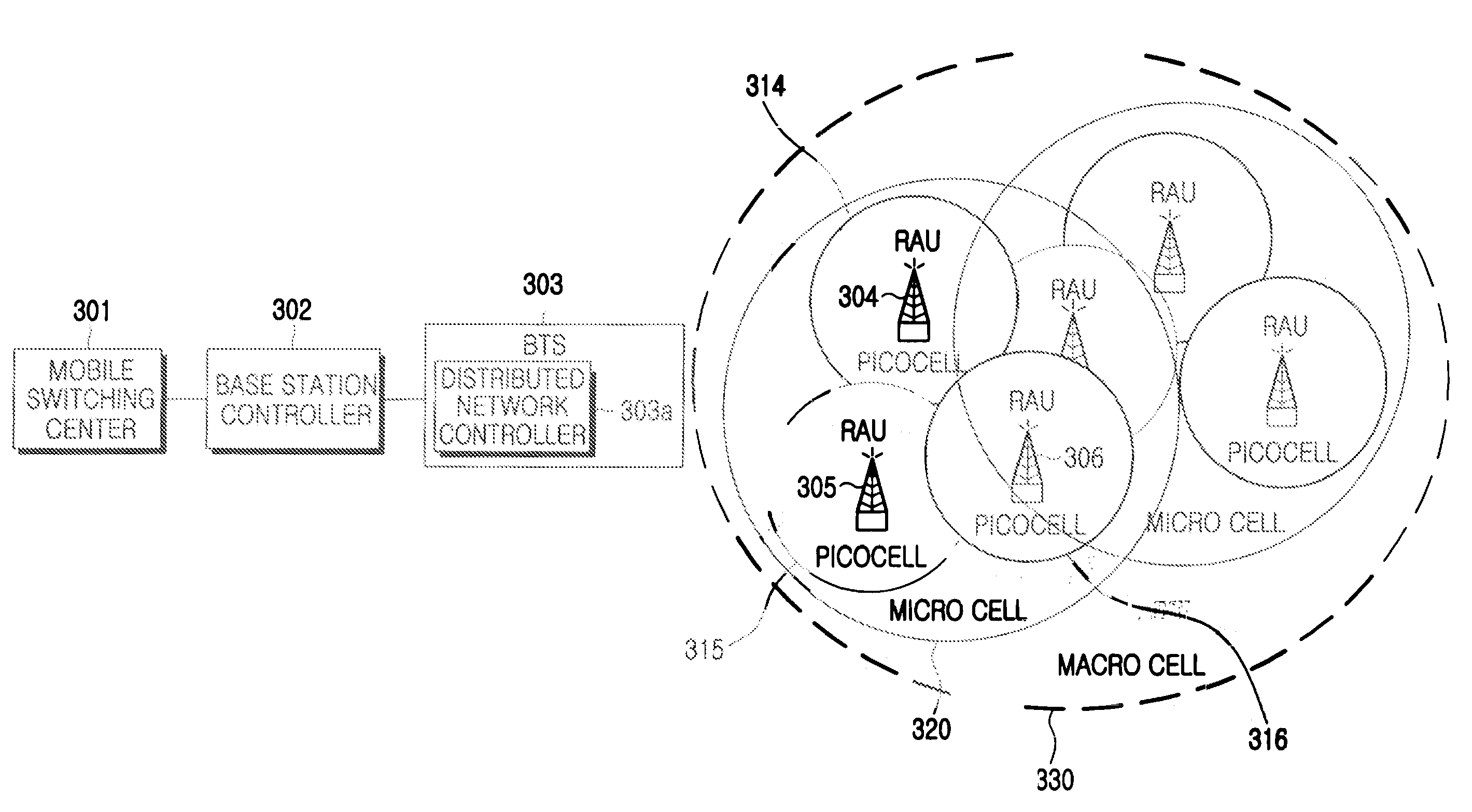
[0049]FIG. 3 illustrates a construction of an optical distributed network system using multi-input multi-output (MIMO) system according to an exemplary embodiment of the present invention.

[0050]Referring to FIG. 3, the inventive optical distributed network system using the MIMO includes a mobile switching center (MSC) 301; a base station controller (BSC) 302; a base station transceiver subsystem 303 including a distributed network controller 303A; and radio access units 304, . . . , 306.

[0051]The optical distributed network system using the MIMO will be described in more detail...


PUM


Abstract

A method for controlling a handoff in an optical distributed network system using MIMO (multi input multi output) is disclosed. The method includes steps of classifying a channel into a first channel and a second channel, and setting an active cell, receiving and measuring a signal strength of a predetermined cell, and determining on / off of the predetermined cell, when the predetermined cell turns on, releasing the first channel of the active cell, switching a path to a first channel of the predetermined cell, and keeping the second channel of the active cell, receiving and measuring a signal strength of the active cell, and when the measured signal strength is a preset critical value or less, turning off the active cell and when the active cell turns off, releasing the second channel of the active cell, and switching the path to a second channel of the predetermined cell.

Description

CLAIM OF PRIORITY[0001]This application claims the benefit of the earlier filing date, under 35 U.S.C. §119, to that patent application entitled “Method For Controlling Handoff In Optical Distributed Network System Using Multi Input Multi Output,” filed in the Korean Intellectual Property Office on Feb. 14, 2006 and assigned Serial No. 2006-14368, the contents of which are incorporated herein by reference.BACKGROUND OF THE INVENTION[0002]1. Field of the Invention[0003]The present invention relates to a method for controlling a handoff in an optical distributed network system, and in particular, to a method for controlling a handoff in an optical distributed network system using multi input multi output (MIMO).[0004]2. Description of the Related Art[0005]Since the late 1970s the U.S. has developed a cellular mobile communication system. Korea is now beginning to provide a voice communication service by an advanced mobile phone service (AMPS) method that is based on an analogous 1st g...

Claims


Application Information

Patent Timeline
Patent Type & Authority Applications(United States)
IPC IPC(8): H04B7/212H04W36/18
CPCH04W36/18H04W36/302H04B7/0413
Inventor CHOI, DO-INHWANG, SEONG-TAEKOH, YUN JE
Owner SAMSUNG ELECTRONICS CO LTD
Learn More