Color-image forming device and method of controlling the same

a color image and forming device technology, applied in the field of color image forming devices, can solve the problems of insufficient color-drift correction in a single color-image forming device, insufficient use of color-image forming device, and significant deformation of the image quality of the color image to be formed, and achieve the effect of reducing the latency and high quality

Inactive Publication Date: 2006-09-26
RICOH KK
View PDF8 Cites 2 Cited by
  • Summary
  • Abstract
  • Description
  • Claims
  • Application Information

AI Technical Summary

Benefits of technology

[0054]Therefore, according to the present invention, it is possible to provide a color-image forming device, by means of which an image with as high quality as possible can be provided with minimum latency time when the user wishes to use the device. The present invention can be expected to be applied in the fields of, in particular, a color printer, a color facsimile, a color printing apparatus provided with transmission capability, and a color transmission apparatus combining a personal computer and a printer, etc.

Problems solved by technology

In such a color-image forming device, when the positional deviation from the predetermined transfer position generates during the transferring of the toner images of respective colors onto the recording medium, the color drift generates due to misalignment of the toner images and therefore, the image quality of the color image to be formed degrades significantly.
However, a single operation of such a color-drift correction in a single color-image forming device is not satisfactory.
However, the color-drift correction needs a predetermined amount of time (ranging from a few seconds to a few minutes) and therefore, there arises a problem in that the color-image forming device is not ready for use until the color-drift correction is completed even when a user of the device wishes to use it right away.
In addition, in the case when the color-image forming device has not been used for a predetermined period and when such a device is given a task (for example, for printing out), there arises a problem in that the device first begins the color-drift correction operation and thus the printing output cannot be quickly obtained.

Method used


Image

  • Color-image forming device and method of controlling the same
  • Color-image forming device and method of controlling the same
  • Color-image forming device and method of controlling the same

Examples


first embodiment

[0082]FIG. 4 is an operational flow chart of a first embodiment according to the present invention. When the color-image forming device is switched on (S101), a color-drift correction execution interval is set by color-drift correction execution interval setting means (S102). Then, it is determined whether the previously set color-drift correction execution interval is-reached (whether the previously set color-drift correction execution interval has passed) (S103). When it is determined that the color-drift correction execution interval is reached (that the color-drift correction execution interval has passed), the color-drift correction by an automatic color-drift correction means is executed (S104). When the color-image forming device is switched off after S104, the process ends and when the device is not switched off after S104, the process returns to S103 (S105).

[0083]In the above-mentioned first embodiment of the present invention, the color-image forming device is provided wit...

second embodiment

[0085]FIG. 5 is an operational flow chart of a second embodiment according to the present invention. When the color-image forming device is switched on (S201), a color-drift correction execution time is set by color-drift correction execution time setting means (S202). Then, it is determined whether the previously set color-drift correction execution time is reached (S203). When it is determined that the color-drift correction execution time has reached, the color-drift correction by the automatic color-drift correction means is executed (S204). When the color-image forming device is switched off after S204, the process ends and when the device is not switched off after S204, the process returns to S203 (S205).

[0086]In the second embodiment according to the present invention, it is assumed that the color drift due to changes over time is to be corrected as in the first embodiment according to the present invention. However, in contrast to the first embodiment, in the second embodime...

third embodiment

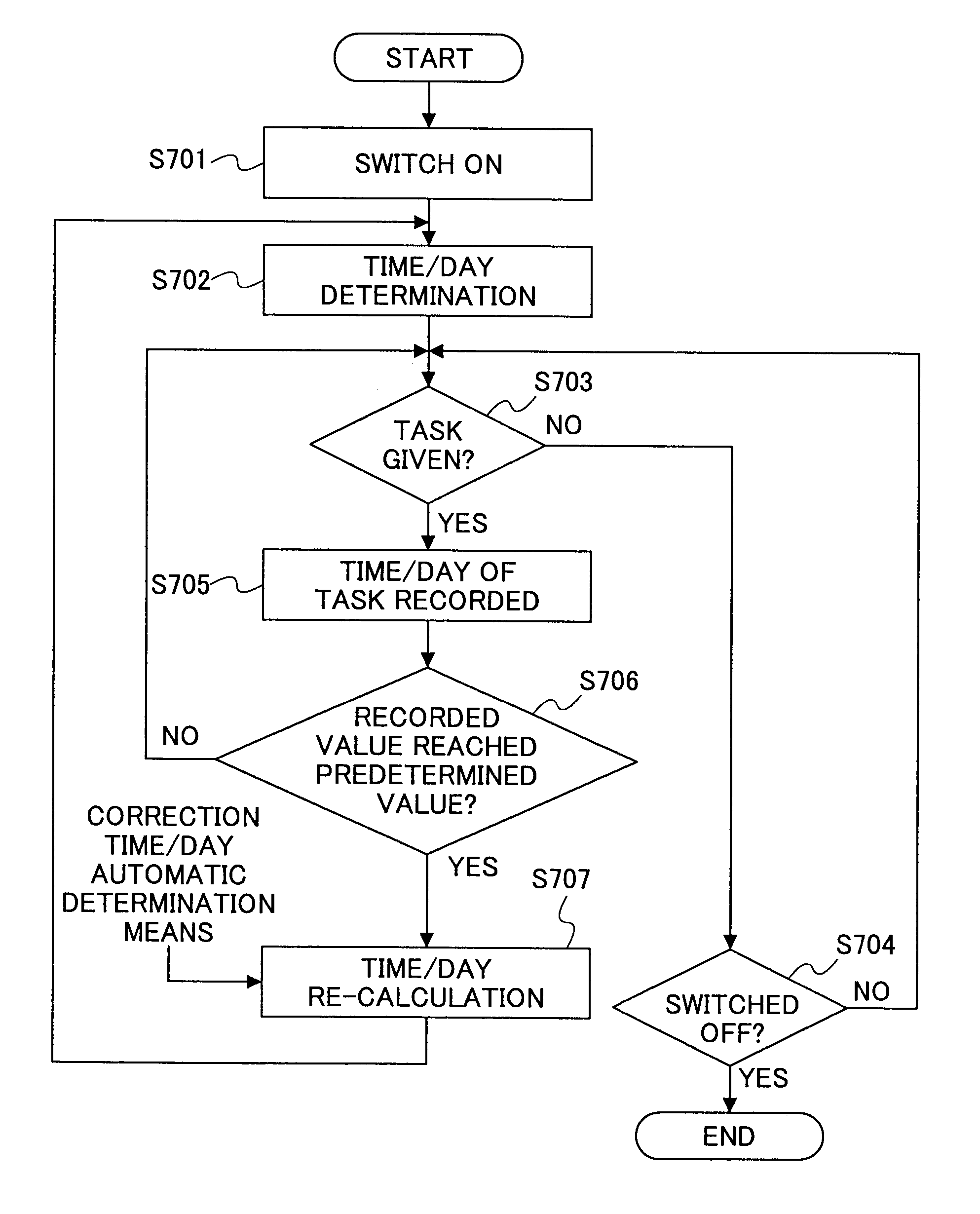
[0088]FIG. 6 is an operational flow chart of a third embodiment according to the present invention. When the color-image forming device is switched on (S301), the color-drift correction execution time is set by the color-drift correction execution time setting means (S302). Then, it is determined whether the set time is reached (S303). When it is determined that the color-drift correction execution time is reached, color-drift correction according to a first correction mode is executed by the automatic color-drift correction means (S304). When the color-image forming device is switched off after S304, the process ends and when the device is not switched off after S304, the process returns to S303 (S307). When it is determined that the color-drift correction execution time is not yet reached in S303, it is determined whether a color-drift correction execution factor is generated (S305). When it is determined that the color-drift correction execution factor is not generated, the proce...


PUM


Abstract

A color-image forming device is provided with: a color-image forming unit for forming a color image by superimposing a plurality of images corresponding to a plurality of colors onto a recording medium. An automatic color-drift correction executes color-drift correction of color drift generated during the superimposition of the images. A color-drift correction execution interval setting unit variably sets the color-drift correction execution intervals, at which intervals the automatic color-drift correction executes the color-drift correction. The functions of the automatic color-drift correction and the color-drift correction execution interval setting unit are realized by the system control unit.

Description

BACKGROUND OF THE INVENTION[0001]1. Field of the Invention[0002]The present invention generally relates to a color-image forming device that forms a color image by sequentially superimposing toner images of respective color components. In particular, the present invention relates to a color-image forming device, by means of which the timing for starting color-drift correction and the timing for canceling color-drift correction can be controlled.[0003]2. Description of the Related Art[0004]Among various color-image forming devices for color image outputs, a color-image forming device that utilizes the electrophotographic process forms the color image using, for example, toners of four different colors, such as Yellow, Magenta, Cyan, and blacK. Unless high position precision is provided when superimposing the toner images of the four colors, color drift, which is the artifact observed on the final color image, may be generated due to the positional deviation of each toner images, and ...

Claims


Application Information

Patent Timeline
Patent Type & Authority Patents(United States)
IPC IPC(8): G03G15/01B41J29/38B41J29/46G03G15/00G03G21/00G03G21/14H04N1/50
CPCH04N1/506
Inventor OHMORI, MASATAKE
Owner RICOH KK
Why Eureka
Try Eureka