
Arch bar

a technology of arch bars and splints, applied in the field of oral and maxillofacial surgery, can solve the problems of trauma to the soft tissue inside the mouth and lips, pain and infection of patients, and the installation of these arch bars takes considerable time, so as to reduce the installation time and thus the operating room time and the associated risk to the patient, and the effect of decreasing general anesthesia

Inactive Publication Date: 2007-08-16
FORE FRANK +1
View PDF15 Cites 11 Cited by
  • Summary
  • Abstract
  • Description
  • Claims
  • Application Information

AI Technical Summary

Benefits of technology

[0011] Therefore, it is an objective of this invention to provide an improved arch bar designed to reduce irritation and trauma to the soft tissue on the inside of the mouth and lips.
[0014] An additional objective is to allow the circumdental wires to pass through the arch bar windows, as well as above and below the arch bar, decreasing installation time and thus operating room time and the associated risk to the patient by decreasing general anesthesia.

Problems solved by technology

These attachment points cause trauma to the soft tissue on the inside of the mouth and lips.
The trauma is a source of discomfort, pain and infection to the patient.
The installation of these arch bars takes considerable time during which the patient is typically under a general anesthetic facing the problems therewith.
The interconnecting by wires is complex and presents jagged outer surfaces that can cause discomfort to the patient.
The exposed ligature wire, as well as the studs, can cut or otherwise traumatize the inside of the mouth.

Method used


Image

  • Arch bar
  • Arch bar
  • Arch bar

Examples


Embodiment Construction

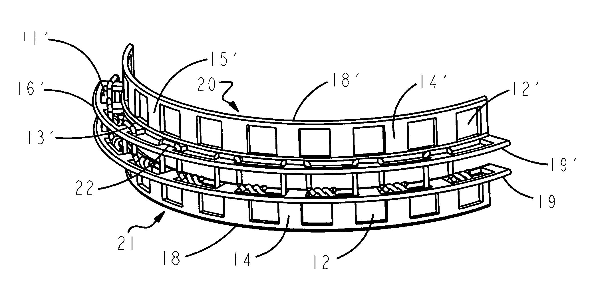
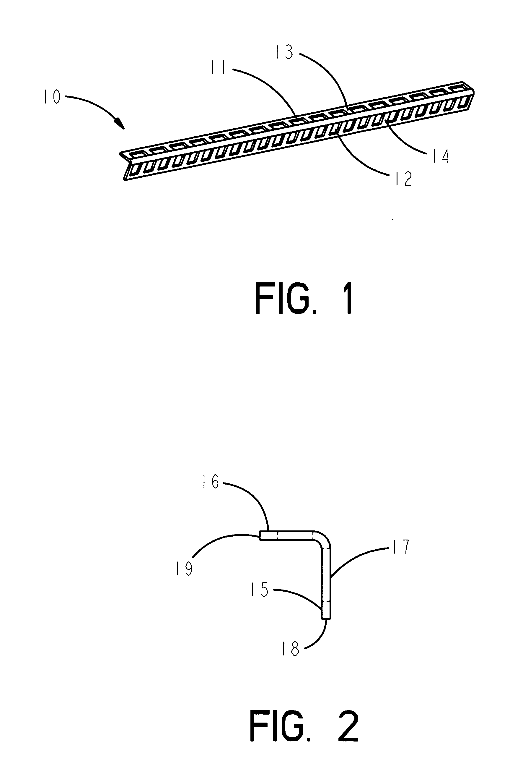
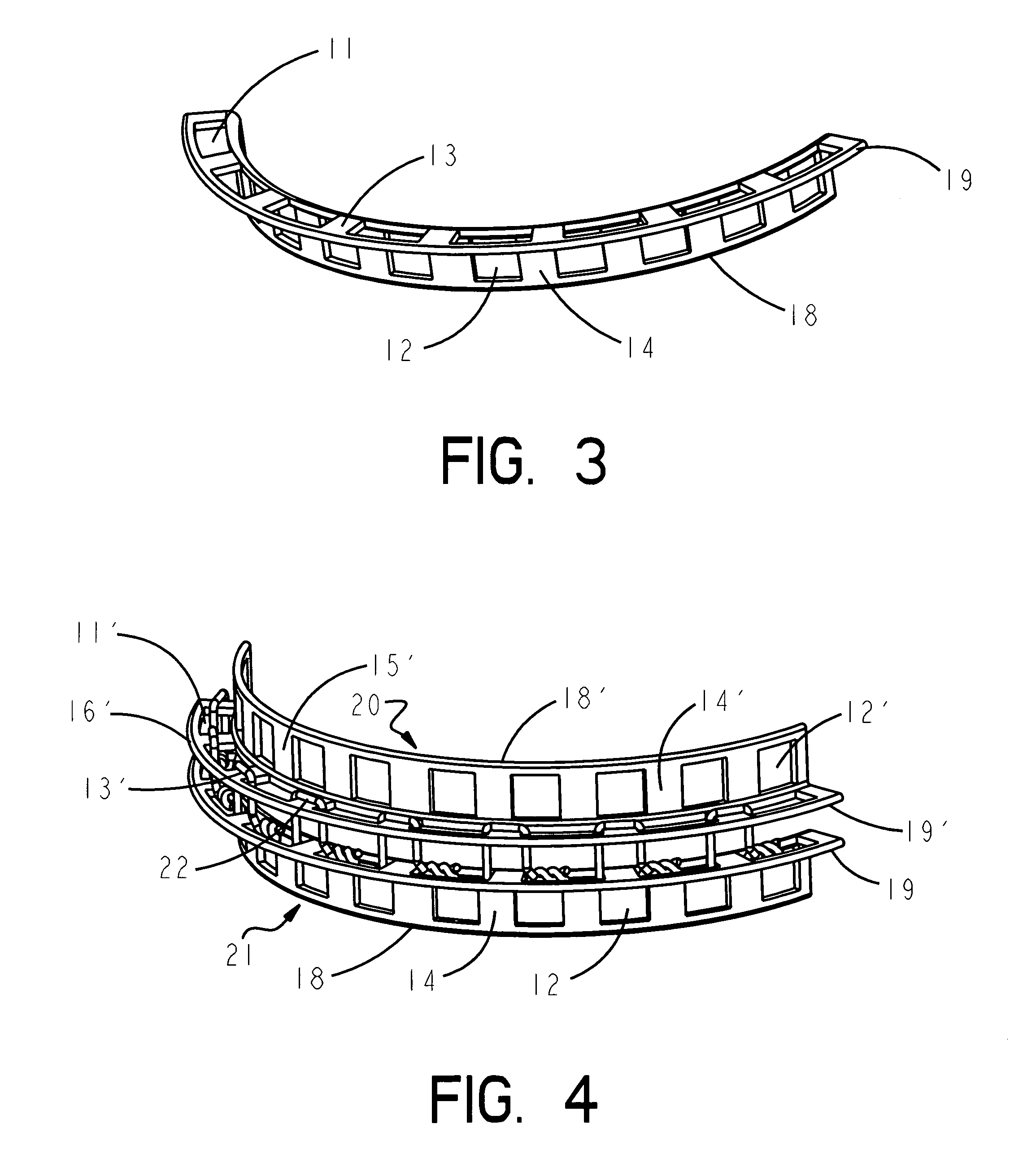
[0020] The arch bar 10, shown in the drawings, is made from a biologically inert material that is malleable into an arcuate shape, such as metals, coated or un-coated with polymers or ceramics; or plastic compositions of sufficient strength to retain the shaped form in the body to prevent relative movement of broken bones or bone fragments. The arch bar has a series of apertures 11 and 12 formed in two rows along the length of the bar. The apertures 11 are separated by partitions 13 and the apertures 12 (pass through windows) are separated by posts 14. The arch bar 10 may be produced and packages as a straight bar, as shown in FIG. 1 or it may be preformed into a large diameter arc. The surgeon will manipulate the bar to its final dimensions as determined by the physiology and injury of the individual patient.

[0021] As shown in FIG. 2, the one piece arch bar has a splint portion 15 and a retainer portion 16 disposed at an angle of approximately 90 degrees. The splint portion 15 has...


PUM


Abstract

An improved arch bar for dental surgery is formed from a strip of malleable material. The strip is the shape of a right angle having a splint portion and a retainer portion. A series of apertures extend through the splint portion and the retainer portion with the longitudinal edges of the strip being continuous and smooth. The splint portion is attached to the bone and the retainer portion forms an outwardly projecting shelf having a smooth surface. The soft tissue of the mouth is protected from ligature wires threaded through the apertures by the shelf.

Description

FIELD OF THE INVENTION [0001] This invention relates to oral and maxillofacial surgery using fixation devices to reduce fractures of the facial bones involving the teeth. BACKGROUND OF THE INVENTION [0002] Conventional practice in reduction or fixation of fractured facial bones involving the teeth and other maxillo-mandibular injuries include placing a splint or arch bar external to the teeth and secured by adhesives or wire to the teeth. An upper bar and a lower bar are connected by wire or flexible elastic bands, as shown by Richter, U.S. Pat. No. 4,230,104. The upper and lower bars have attachment points, called lugs, on the outer surface for the wire or bands. These attachment points cause trauma to the soft tissue on the inside of the mouth and lips. The trauma is a source of discomfort, pain and infection to the patient. [0003] Another conventional way of fixing the upper and lower jaws after corrective maxillomandibular surgery or trauma is by immobilizing either the maxillar...

Claims


Application Information

Patent Timeline
IPC IPC(8): A61C3/00
CPCA61B17/8071A61C5/007A61C5/00A61B17/8085
Inventor FORE, FRANKCASSATLY, MICHAEL
Owner FORE FRANK
Learn More