Fuel reformer
a fuel reformer and fuel technology, applied in the field of fuel reformers, can solve the problems of not reducing both pm and nox, lowering the purification capability, and not being able to reduce the purification capacity, so as to improve the fuel reforming efficiency, reduce the weight of the fuel reformer 1 easily, and reduce the effect of fuel reforming efficiency
Active Publication Date: 2007-08-23
FUJI KIHAN CO LTD
View PDF10 Cites 13 Cited by
- Summary
- Abstract
- Description
- Claims
- Application Information
AI Technical Summary
Benefits of technology
The patent describes a fuel reformer with improved fuel reforming efficiency. By filling the process chamber with catalytic material and achieving a certain surface area, the fuel consumption is reduced. The catalytic material is designed in a hollow state, which allows for easy weight reduction without lowering the fuel reforming efficiency. The metal oxide layer is also formed in an open hole, which expands the surface area in contact with the fuel without increasing the size of the entire fuel reformer. The fuel reformer is designed with a removable lid body and a mesh body to hold the catalytic material securely and prevent play in the process chamber. The technical effects of the patent are improved fuel reforming efficiency, reduced fuel consumption, and easy maintenance of the fuel reformer.
Problems solved by technology
The technical problem addressed in this patent text is to develop a fuel reformer that can efficiently reform fuel in combustion apparatuses such as boilers, heat treat furnaces, and internal combustion engines, reducing emissions of hazardous materials and keeping the fuel consumption rate high. The fuel reformer should also reduce the amount of fuel consumed and the complexity of the fuel system. The invention aims to provide a fuel reformer that can be used in various combustion apparatuses while keeping the advantageous characteristics of the fuel reformer in Japanese Unexamined Patent Publication No. The invention also aims to reduce emissions of nitrogen oxide, particulate material, and carbon dioxide generated with operation of the combustion apparatus.
Method used
View moreImage
Smart ImageViewing Examples
Examples
 PUM
| Property | Measurement | Unit |
|---|---|---|
| Fraction | aaaaa | aaaaa |
| Surface area | aaaaa | aaaaa |
| Particle diameter | aaaaa | aaaaa |
Abstract
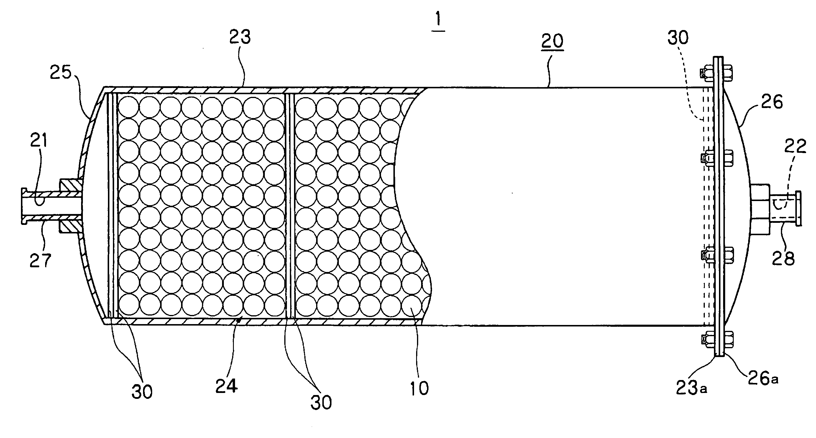
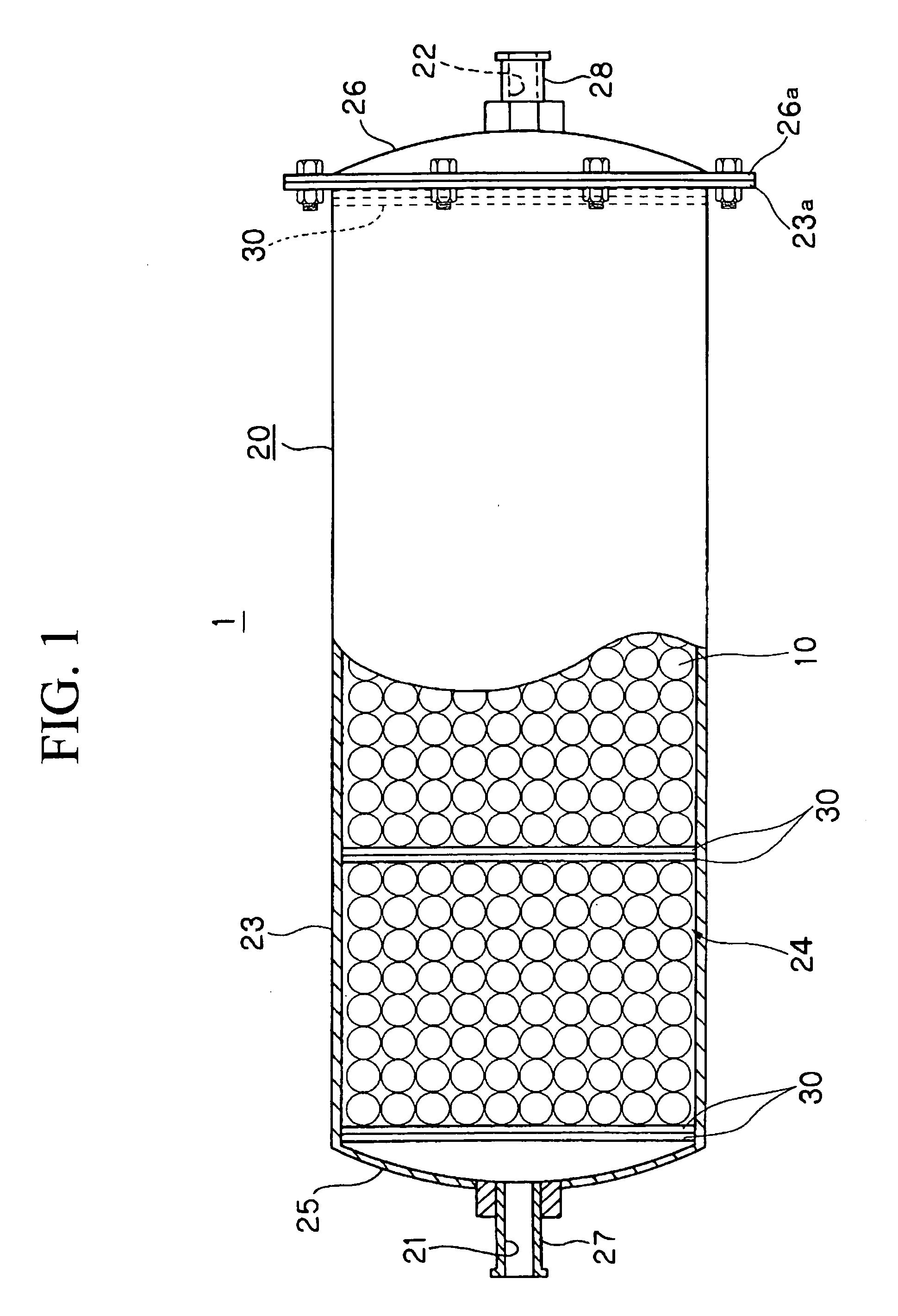
A fuel reformer which can improve fuel cost is provided. The fuel reformer 1 is formed by filling a granular catalytic material 10 provided with a metal oxide layer having an oxygen deficit tilting structure formed on the surface by shot peening in a process chamber 24 formed in a casing 20 having a fuel inlet 21 and an outlet 22.
The fuel introduced into this fuel reformer 1 is activated by contact with the metal oxide layer 12 formed on the surface of said catalytic material 10 so that the fuel cost of the combustion apparatus to which the fuel is supplied is improved.
Description
Login to View More Claims
Login to View More Application Information
Patent Timeline
 Owner FUJI KIHAN CO LTD
Features
- R&D
- Intellectual Property
- Life Sciences
- Materials
- Tech Scout
- Unparalleled Data Quality
- Higher Quality Content
- 60% Fewer Hallucinations
Learn More Browse by: Latest US Patents, China's latest patents, Technical Efficacy Thesaurus, Application Domain, Technology Topic, Popular Technical Reports.
© 2025 PatSnap. All rights reserved.Legal|Privacy policy|Modern Slavery Act Transparency Statement|Sitemap|About US| Contact US: help@patsnap.com


