
Ultrasonic/sonic jackhammer

a technology of ultrasonic jackhammer and jackhammer head, which is applied in the field of ultrasonic/sonic jackhammer, can solve the problems of limiting its application, and requiring large axial force and large holding torqu

Active Publication Date: 2007-08-23
CALIFORNIA INST OF TECH
View PDF61 Cites 17 Cited by
  • Summary
  • Abstract
  • Description
  • Claims
  • Application Information

AI Technical Summary

Benefits of technology

[0007] The present invention provides an apparatus aimed at providing fracturing impact that spares flexible structures by the use of ultrasonic and sonic vibrations. In one aspect, the invention relates to an apparatus that includes a piezoelectric actuator configured to generate vibrations at a resonance ultrasonic frequency, and a solid impactor configured to be displaced by the vibrations genera

Problems solved by technology

There are many drawbacks associated with the use of a pneumatic jackhammer that limit its applications.
One of these drawbacks is the enormous acoustic noise that makes its use outside normal work hours nearly prohibitive in residential neighborhoods.
Another drawback involves the violent back-pulsations during the operation of a pneumatic jackhammer, which require large axial forces and large holding torques during operation.
In addition, the back-pulsations that propagate into the hand and body of the operators can cause severe damage and pose serious work hazards.
The cutting action by a pneumatic jackhammer is indiscriminate and every object it encounters along its path will be damaged.
In utilities maintenance work, for example, this drawback becomes critical since it is imperative for workers to avoid damaging wires, plumbing conduits, reinforcement rebar and other fixtures.
These and other drawbacks such as high power consumption not only limit the conventional jackhammer's use in construction and utility maintenance, but also in medical surgeries, robotic operations, archeology, and geological explorations including space expeditions.
Specifically for space expeditions, since many planets or other celestial bodies do not have as large an atmospheric pressure as is present on the Earth, it would be difficult to produce the type of pneumatic forces that are generated on the Earth to drive a conventional jackhammer.

Method used


Image

  • Ultrasonic/sonic jackhammer
  • Ultrasonic/sonic jackhammer
  • Ultrasonic/sonic jackhammer

Examples


Embodiment Construction

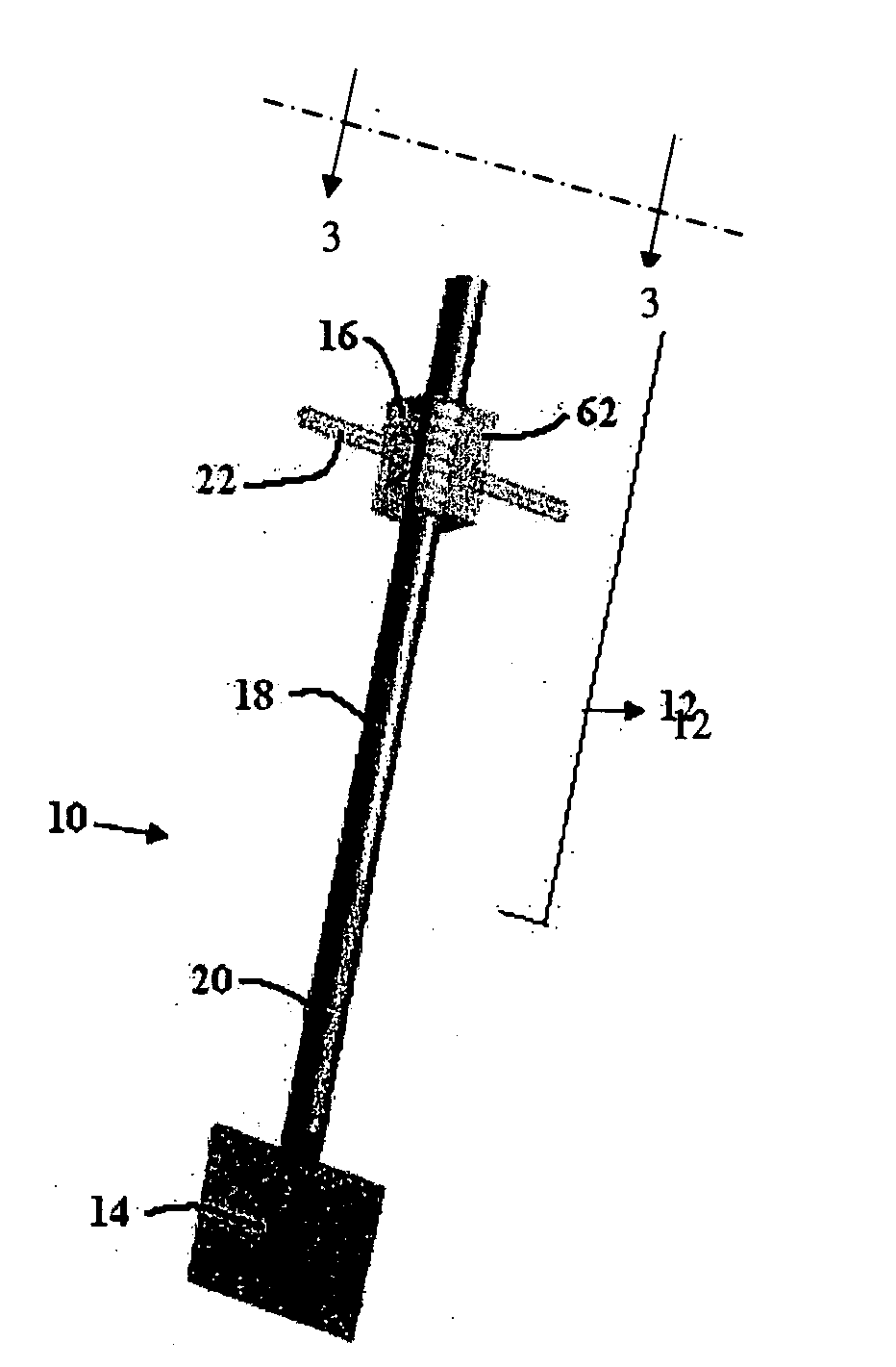
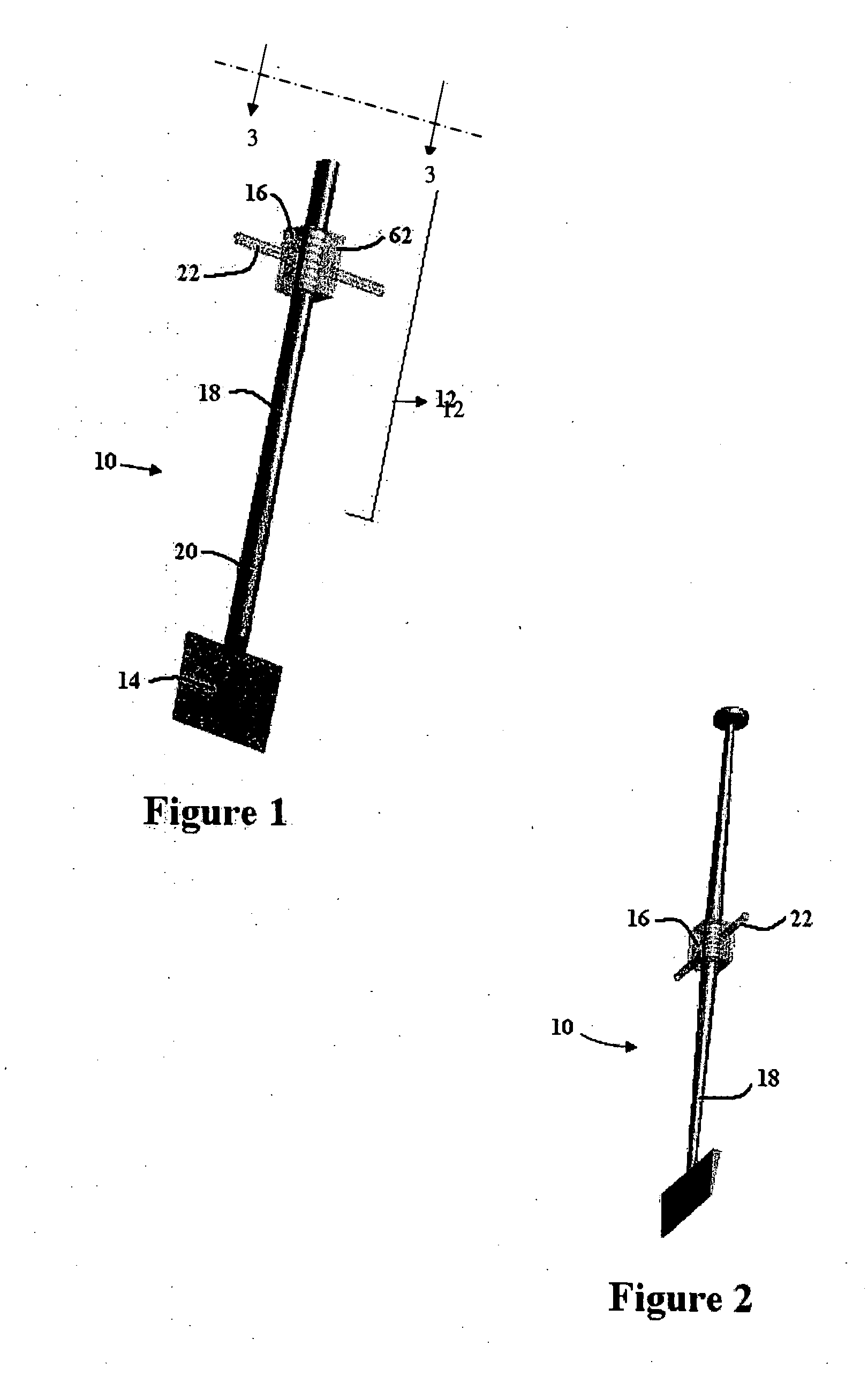
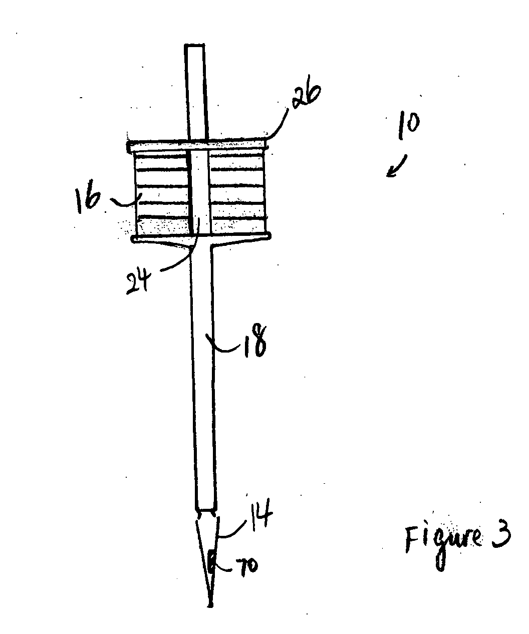
[0031] The present invention provides a new type of jackhammer that utilizes ultrasonic and / or sonic vibrations to power the impacting bit for fracturing relatively brittle surfaces such as rocks and concrete. The new jackhammer disclosed herein uses a hammering mechanism that fractures brittle structures without causing damage to embedded flexible / ductile materials and structures. Further, the new jackhammer generates minimal back-pulsation that propagates back onto the mounting fixture, and requires little axial force or holding torque. As a result, it enables uses in conjunction with lightweight platforms such as those provided by certain robots and rovers in space missions, and also eliminates risks of injury to the operator. The present invention provides embodiments where the handle or the casing of the jackhammer remains virtually vibration-free during operation. Furthermore, apparatuses of the invention are significantly quieter than pneumatic systems, allowing uses in resid...


PUM


Abstract

The invention provides a novel jackhammer that utilizes ultrasonic and / or sonic vibrations as source of power. It is easy to operate and does not require extensive training, requiring substantially less physical capabilities from the user and thereby increasing the pool of potential operators. An important safety benefit is that it does not fracture resilient or compliant materials such as cable channels and conduits, tubing, plumbing, cabling and other embedded fixtures that may be encountered along the impact path. While the ultrasonic / sonic jackhammer of the invention is able to cut concrete and asphalt, it generates little back-propagated shocks or vibrations onto the mounting fixture, and can be operated from an automatic platform or robotic system.

Description

CROSS-REFERENCE TO RELATED APPLICATIONS [0001] This application claims priority to and the benefit of U.S. provisional patent application Ser. No. 60 / 765,153, filed Feb. 3, 2006, which application is incorporated herein by reference in its entirety.STATEMENT REGARDING FEDERALLY SPONSORED RESEARCH [0002] The invention described herein was made in the performance of work under a NASA contract, and is subject to the provisions of Public Law 96-517 (35 USC 202) in which the Contractor has elected to retain title.FIELD OF THE INVENTION [0003] The invention relates generally to devices that utilize ultrasonic and / or sonic vibrations, and more specifically to devices that use such vibrations for impact, probing, analysis or exploration purposes. BACKGROUND OF THE INVENTION [0004] Jackhammers are often used to open up or fracture a hard surface, such as concrete cement and rock formations. They are widely used in construction sites for preparation work, demolition and removal of concrete sl...

Claims


Application Information

Patent Timeline
IPC IPC(8): B25D11/00
CPCB25D11/064Y10S173/02B25D11/00B25D2250/311
Inventor BAR-COHEN, YOSEPHSHERRIT, STEWARTHERZ, JACK L.
Owner CALIFORNIA INST OF TECH
Learn More