Multifunctional restrictive valve

a restrictive valve and multi-functional technology, applied in the direction of valve operating means/release devices, process and machine control, etc., can solve the problems of increasing both water costs and heating costs, wasting a lot of water and energy each year, and simply losing a significant amount of hot water down the drain, etc., to achieve novel functions and advantages, save water and energy, and reduce the amount of hot water wasted

Active Publication Date: 2007-08-23
EVOLVE TECH
View PDF15 Cites 16 Cited by
  • Summary
  • Abstract
  • Description
  • Claims
  • Application Information

AI Technical Summary

Benefits of technology

[0007] Thus, the device is designed to conserve water and energy by reducing the amount of hot water wasted during the time the person first turns on the water and when they actually enter the shower (the warm-up period). Applicant's novel valve accomplishes this by restricting or stopping the water flow from the shower once the water has reached a suitable showering temperature. However, the user is allowed to resume the flow of water and actually ready to begin using it.
[0008] Applicant's valve achieves its novel functions and advantages through the use of a water temperature controlled mechanism, including a piston, temperature sensor and water flow ports (for example, in a slide), that provides for shutoff when water temperature reaches above a predetermined temperature to avoid wasting hot water. However, the

Problems solved by technology

Additionally, vast amounts of water and energy are wasted each year due to the delay in receiving water at the correct temperature.
That is, as most individuals are reluctant to stand by the shower and continuously monitor the water temperature for ma

Method used


Image

  • Multifunctional restrictive valve
  • Multifunctional restrictive valve
  • Multifunctional restrictive valve

Examples


Embodiment Construction

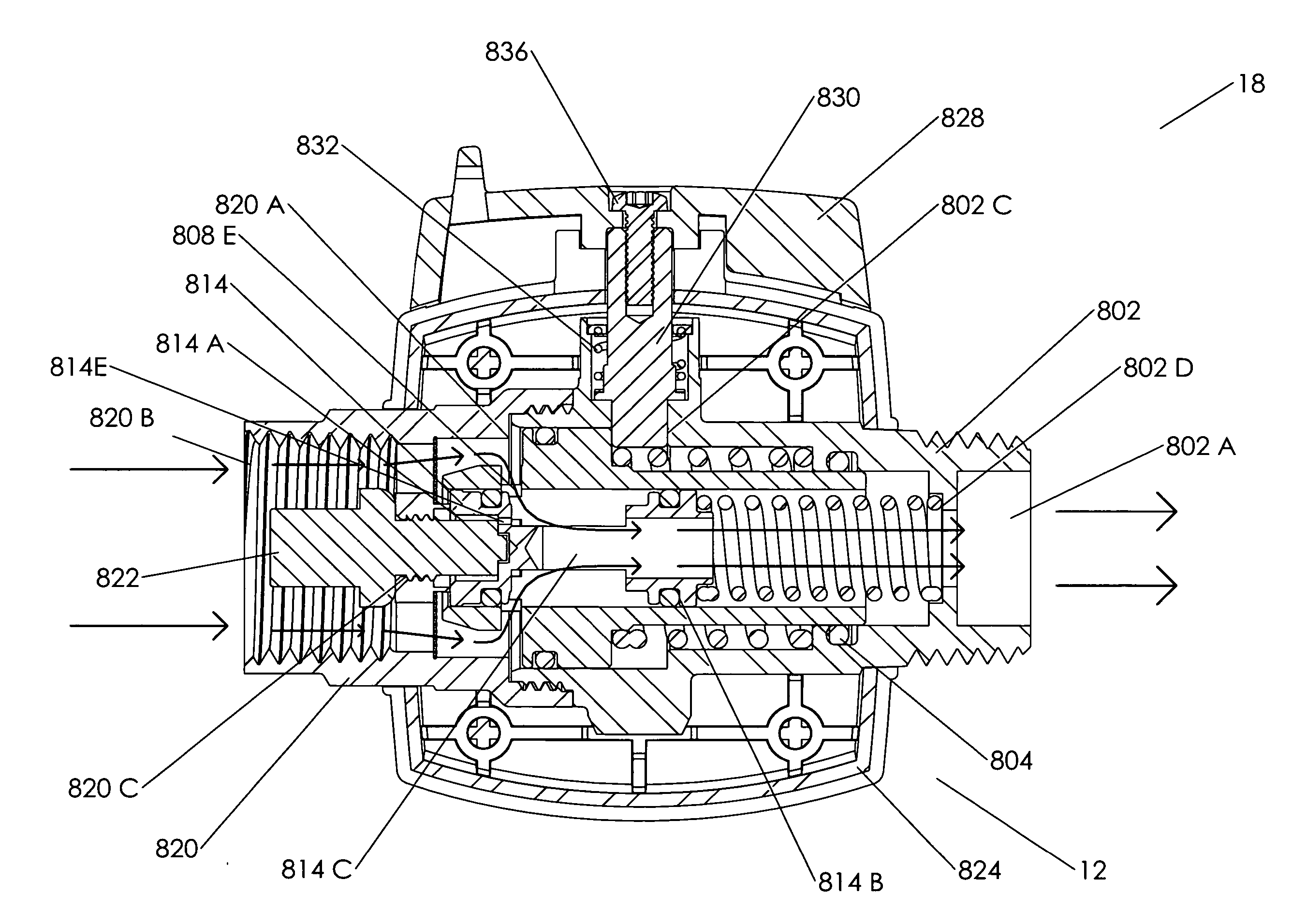
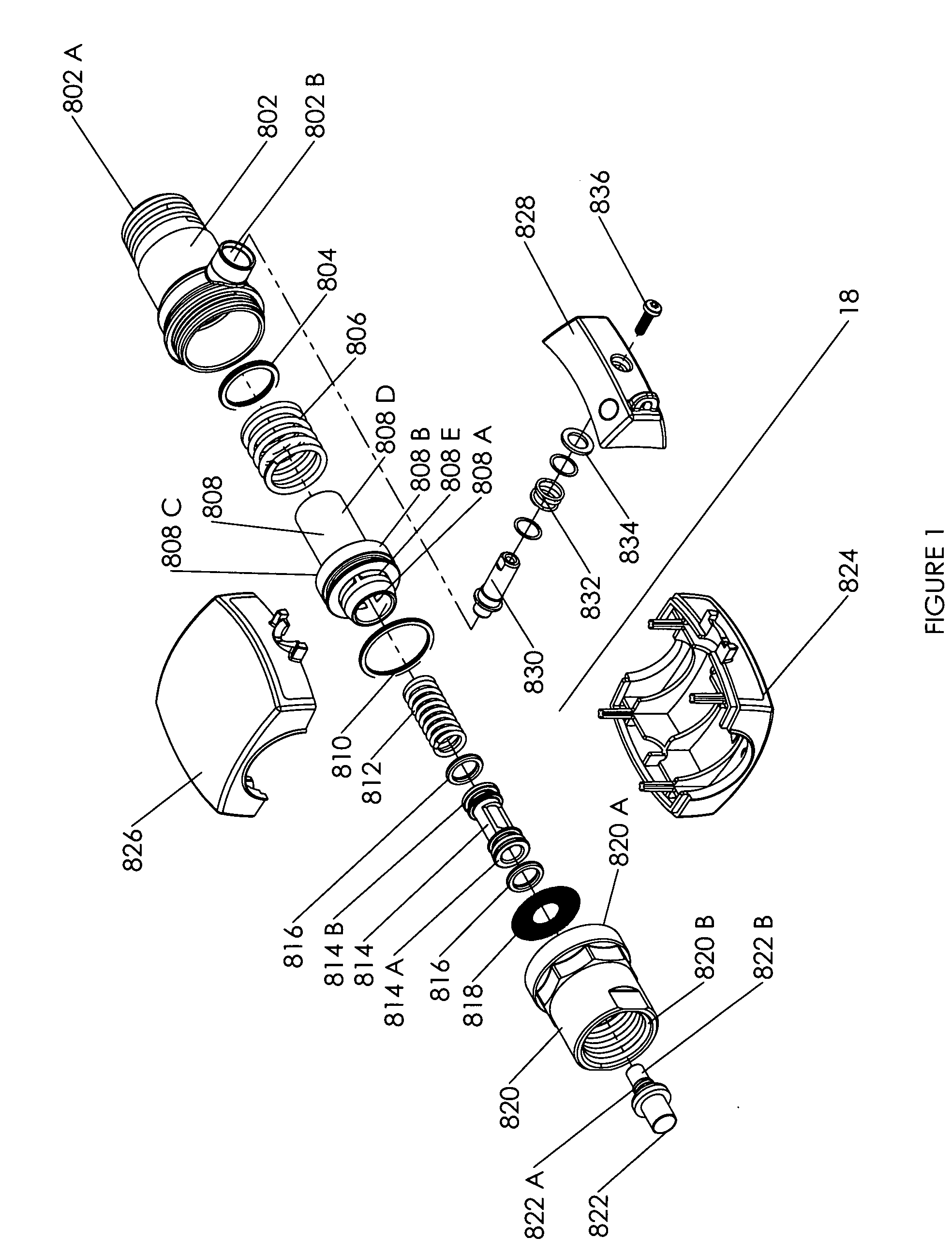
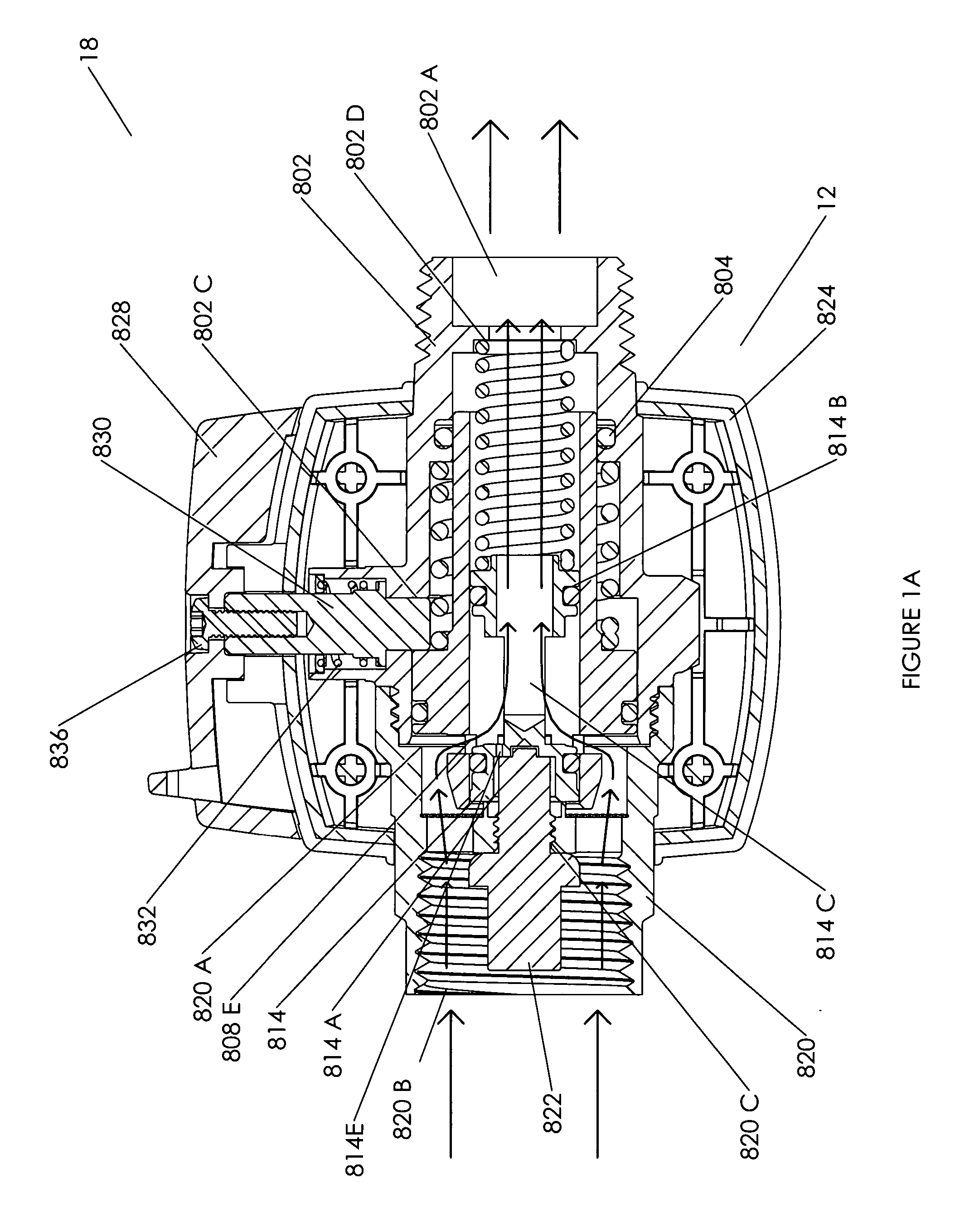
[0025] Referring now to FIGS. 1-5B, there is shown an exploded view of a first embodiment of the present invention assembly. The valve assembly 18 is comprised of the following components: a main body rear 802, a main body O-ring 804, a slide spring 806, a slide 808, a slide O-ring 810, a piston spring 812, a piston 814, two piston O-rings 816, a screen 818, a body front 820, an actuator 822, a release pin 830, a release pin spring 832, and a pin retention ring 834. The valve assembly housing 12 is comprised of the following components: a housing first part 824, a housing second part 826, and a handle 828.

[0026] The main body O-ring 804, slide spring 806, and the longer end of the slide 808 are operably inserted into the wider, threaded end of the body rear 802. The main body is comprised of body rear 802 and body front 820. The piston spring 812, a first piston O-ring 816, the piston 814, and a second piston O-ring 816 are operably inserted into the wider, threaded end of the body...


PUM


Abstract

A multifunctional restrictive valve for controlling the flow of water therethrough. The valve has a main body with a flow channel through the main body. The main body receives water upstream thereof through an inlet port and passes it out through an outlet port at the downstream end of the body. A flow control assembly is located in the flow channel and includes a temperature sensor/actuator acting on a piston to move, when the temperature sensor heats up the piston, to block water flow control ports. The flow control assembly also includes an override feature wherein the piston is located within a slide and the flow control ports are located in the slide. By moving the slide away from the piston when the piston is blocking the flow control ports, the temperature sensor and piston may be overridden and flow may resume through the main body.

Description

PRIORITY CLAIM [0001] This application claims priority from U.S. Provisional Patent Application Ser. No. 60 / 794,735, entitled “TEMPERATURE CONTROLLED RESTRICTIVE VALVE” filed Apr. 25, 2006, the specification and drawings of which are incorporated herein by reference. This application is a continuation-in-part of and claims priority from U.S. patent application Ser. No. 11 / 154,404, filed Jun. 15, 2005, the specifications of which are incorporated herein by reference.FIELD OF THE INVENTION [0002] The present invention is generally related to restrictive valves, and more specifically to controlled fluid flow restrictive valves with a temperature controlled cutoff port, including a resettable release mechanism for overriding the temperature controlled flow cutoff port. BACKGROUND OF THE INVENTION [0003] It is often necessary, in both consumer and commercial contexts, to wait for a water source to reach a suitable temperature prior to use. For example, it is very common for an individual...

Claims


Application Information

Patent Timeline
IPC IPC(8): G05D23/13G05D23/02F16K35/06
CPCE03C1/0408E03C1/044E03C2001/0418E03C1/04F16K31/002G05D23/022F16K1/123Y02A20/40Y10T137/7737F16K3/24
Inventor BROWN, MICHAELLOCKHART, JOHNDOSS, JEFFREY S.
Owner EVOLVE TECH
Why Eureka
Try Eureka