Low friction butterfly ring

a butterfly valve and low friction technology, applied in the field of low friction butterfly valves, can solve the problems of wear on the outside edge of the rings and/or inside, further contact and friction between the rings and bores, etc., and achieve the effect of minimizing the leakage of the butterfly valv

Active Publication Date: 2007-08-23
GE AVIATION SYST LLC
View PDF13 Cites 8 Cited by
  • Summary
  • Abstract
  • Description
  • Claims
  • Application Information

AI Technical Summary

Benefits of technology

[0007] The present inventor has determined that due to expansion of the rings, when the butterfly valve is in an open position, a conventional butterfly valve ring will expand to a diameter that is larger than the bore of a housing or passage. Subsequently, when the butterfly valve is closed, the rings will be forced against the inside bore of the housing or passage, causing contact and friction between the rings and bore during actuation of the valve. This contact and friction will increase as the fluid pressure between the rings and butterfly disc increases. Contact and friction between the rings and bore causes wear on the outside edge of the rings and / or inside the bore almost each time the valve is actuated. Rings of conventional butterfly valves will expand or be forced outwards to accommodate this wear of the outside edge of the rings and / or bore, causing further contact and friction between the rings and bore. Therefore, as the rings and / or bores of conventional butterfly valves wear, the rings will continue to expand or be forced outwards to accommodate this wear so that the rings can continue to engage and press against the bore of the housing or passage, minimizing leakage of the butterfly valve. However, this continued compensation for wear causes the wear of the rings and / or bore to continue, causing the rings and / or bore to eventually wear out and the butterfly valve to lose effectiveness.
[0010] In an exemplary embodiment of the present invention, there is a method of configuring a butterfly valve within a passage or bore such that wear and friction resulting from repeated actuation of the valve is reduced and / or eliminated, at least after the initial relatively limited number of actuations of the valve after installation (relative to the expected total number of actuations during the life of the valve). According to this method, initially, one or more rings are positioned within a ring groove that is formed by (between) a ring retainer that is connected to the butterfly. The ring(s) are initially permitted to float within the ring groove, the ring(s) being in the most expanded position or about the most expanded position at this point in the installation process. That is, the ring retainer is not yet fully attached to the butterfly, thus creating a gap where minimal to no clamping force is applied to the ring(s), permitting the rings to effectively freely expand and contract in the radial direction (i.e., the outer diameter of the rings may get larger and smaller if contraction and expansion forces are applied to the ring, respectively). The butterfly valve is then placed into the passage or bore and moved to the closed position, thus contracting the outer diameter of the ring(s) to the diameter of the bore. Then, the ring retainer is fully attached to the butterfly so that the ring(s) are restrained and effective outward radial expansion of the ring(s) is prevented or substantially prevented. Thereafter, when the butterfly valve is actuated to the open position, the ring(s) are restrained so that effective expansion of the ring(s) is prevented, causing the outward radial expansion of the ring(s) to be prevented or substantially prevented. In this way, the butterfly valve can be adapted to lock the ring(s) in position so that the ring(s) cannot substantially move with respect to the butterfly, nor can the ring(s) substantially expand when the butterfly valve is in the open position. In this manner, by substantially limiting the expansion of the rings caused by a reduction in compressive force applied by the bore diameter when the valve is moved to the open position, wear and friction on the rings may be substantially reduced and / or completely eliminated. Furthermore, by configuring a butterfly valve using this method, the ring(s) can be configured to be positioned in the center of a bore and the butterfly valve can adequately fit within the bore without friction or substantially without friction.
[0011] It is noted that in another embodiment of the present invention, instead of installing the butterfly valve in the bore with the rings in the expanded position, the rings may be first contracted to have a diameter smaller than that of the bore and clamped in the groove with the retainer (e.g., the retainer is fully attached to the butterfly) to maintain the smaller diameter. Then, the butterfly valve is placed in the bore in the closed position, whereupon the retainer is loosened from the butterfly (e.g., the retainer is no longer fully attached to the butterfly), permitting the ring(s) to expand to the diameter of the bore. The retainer is then again fully attached to the butterfly to clamp the rings in place, thus effectively locking in the diameter of the ring(s).

Problems solved by technology

Subsequently, when the butterfly valve is closed, the rings will be forced against the inside bore of the housing or passage, causing contact and friction between the rings and bore during actuation of the valve.
Contact and friction between the rings and bore causes wear on the outside edge of the rings and / or inside the bore almost each time the valve is actuated.
Rings of conventional butterfly valves will expand or be forced outwards to accommodate this wear of the outside edge of the rings and / or bore, causing further contact and friction between the rings and bore.
However, this continued compensation for wear causes the wear of the rings and / or bore to continue, causing the rings and / or bore to eventually wear out and the butterfly valve to lose effectiveness.
If wear resistant materials are used, the cost of the valve will be increased, as such materials are more expensive than conventional materials and it is more difficult to manufacture parts from these materials.
However, the extra step of plating the parts of the butterfly valve presents an added step in manufacturing, along with added material costs and present hazardous material problems.

Method used


Image

  • Low friction butterfly ring
  • Low friction butterfly ring
  • Low friction butterfly ring

Examples


Embodiment Construction

[0043] Embodiments of the present invention will be described below with reference to the drawings.

[0044] According to an embodiment, a butterfly valve and butterfly valve assembly are provided in which the butterfly valve is adapted to operate without friction or substantially without friction when the butterfly valve is placed in a closed position.

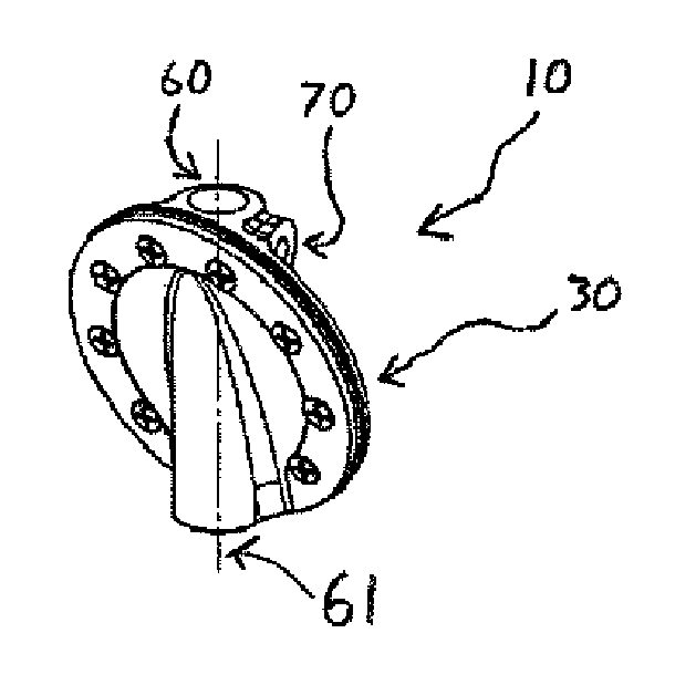
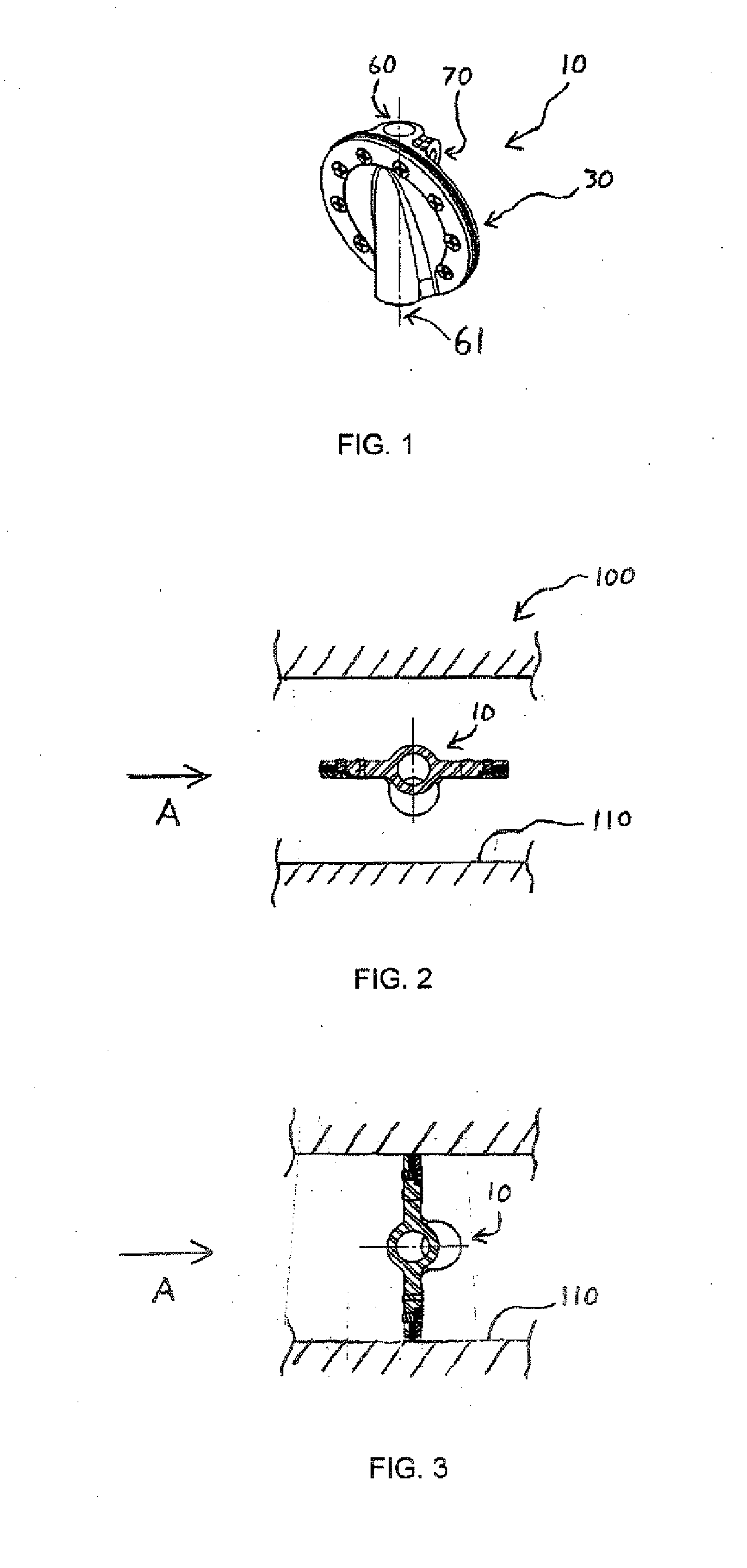
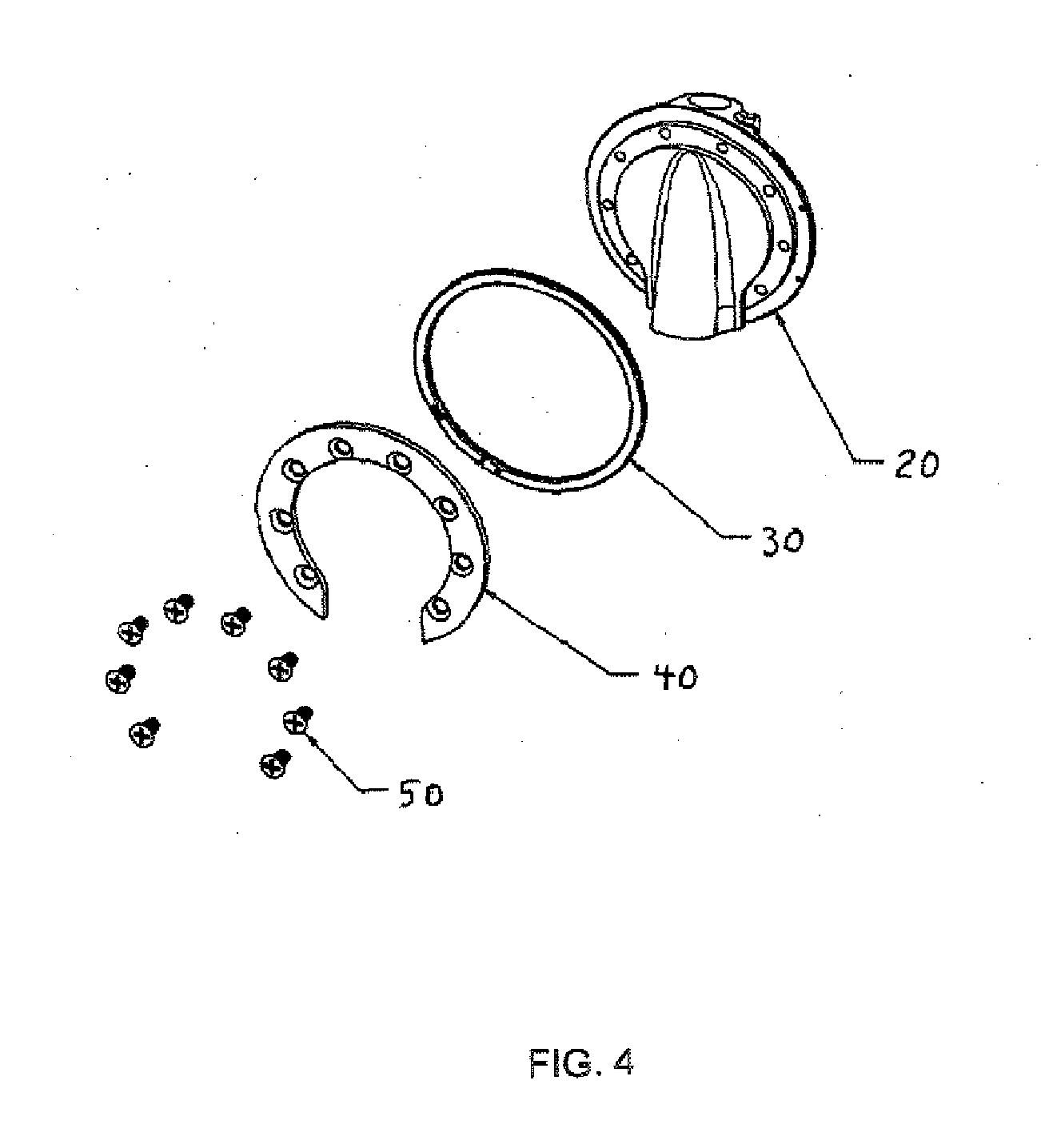
[0045]FIG. 1 shows a perspective view of a butterfly valve 10, according to an embodiment. In the example shown in FIG. 1, the butterfly valve 10 includes at least one ring 30, and a passage 60 for a shaft (not shown) to support and rotate the butterfly valve 10 in a butterfly valve assembly (i.e. the butterfly valve 10 rotates about axis 61). In the example shown in FIG. 1, the butterfly valve 10 includes a receptacle 70 for a device to position the butterfly valve 10 on the shaft. The butterfly valve 10 can be positioned on the shaft with, for example, a set screw, pin, or other fastening device known in the art. The rings 30 used wi...


PUM

PropertyMeasurementUnit
diameteraaaaaaaaaa
diameteraaaaaaaaaa
pressureaaaaaaaaaa

Abstract

A butterfly valve for controlling the flow of fluid within a bore, including a butterfly and at least one ring extending at least one of substantially and completely around a perimeter of the butterfly and adapted to develop an expansion force in the radial direction when the at least one ring is in a contracted state with respect to the radial direction, wherein the at least one ring is secured to the butterfly in the contracted state and radial expansion due to the developed expansion force of the at least one ring is effectively restrained, wherein the butterfly valve is adapted to operate, when placed in a bore, without friction or substantially without friction between the at least one ring and the bore when the butterfly valve is placed in a closed position within the bore.

Description

BACKGROUND [0001] Butterfly valves are one of many types of valves that are used to control the flow of fluids. A conventional butterfly valve includes a disc (also called a butterfly), that is rotated within a housing bore or passage to block fluid flow in varying amounts. Typically, the disc is mounted to turn on an axis that traverses the housing bore or passage so that the disc can rotate between an open position and a closed position. When the disc is in the open position, the plane of the disc is generally coincident or parallel to the direction of flow and the fluid flow rate is maximized. When the disc is in the closed position, the plane of the disc is transverse / orthogonal to the direction of flow and the fluid flow rate is minimized or completely stopped. [0002] Conventional butterfly valves further include a fluid seal that is provided, for example, by the outer edge of the disc or by a sealing member, such as, for example, one or more butterfly rings, that is / are attach...

Claims


Application Information

Patent Timeline
Patent Type & Authority Applications(United States)
IPC IPC(8): F16K1/22
CPCY10T29/49412F16K1/2261Y10T137/0525
Inventor SHENK, DAVID R.
Owner GE AVIATION SYST LLC
Why Eureka
Try Eureka