RFID antenna system having reduced orientation sensitivity

a technology of rfid antenna and orientation sensitivity, which is applied in the direction of polarised antenna unit combination, burglar alarm mechanical actuation, instruments, etc., can solve the problems of power loss, difficulty in adjusting the orientation, and reducing the utility of the reader, so as to achieve less sensitive to orientation

Active Publication Date: 2007-08-23
DATALOGIC MOBILE
View PDF24 Cites 66 Cited by
  • Summary
  • Abstract
  • Description
  • Claims
  • Application Information

AI Technical Summary

Benefits of technology

[0007] Various embodiments are described herein directed to systems and methods for making RFID antennas less sensitive to orientation. According to one embodiment, an electromagnetic tag reader comprises a plurality of linearly polarized antennas, a control circuit, and transceiver circuitry. The plurality of linearly polarized antennas has at least a first antenna and a second antenna arranged non-parallel to the

Problems solved by technology

If the received signal strength is not optimal, the distance between the tag reader and the tag must be reduced for continued operation of the tag, thus decreasing the utility of the reader.
However, these types of RFID readers have had to sacrifice approximately half their power output to do s

Method used


Image

  • RFID antenna system having reduced orientation sensitivity
  • RFID antenna system having reduced orientation sensitivity
  • RFID antenna system having reduced orientation sensitivity

Examples


Embodiment Construction

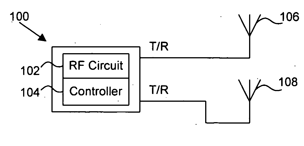
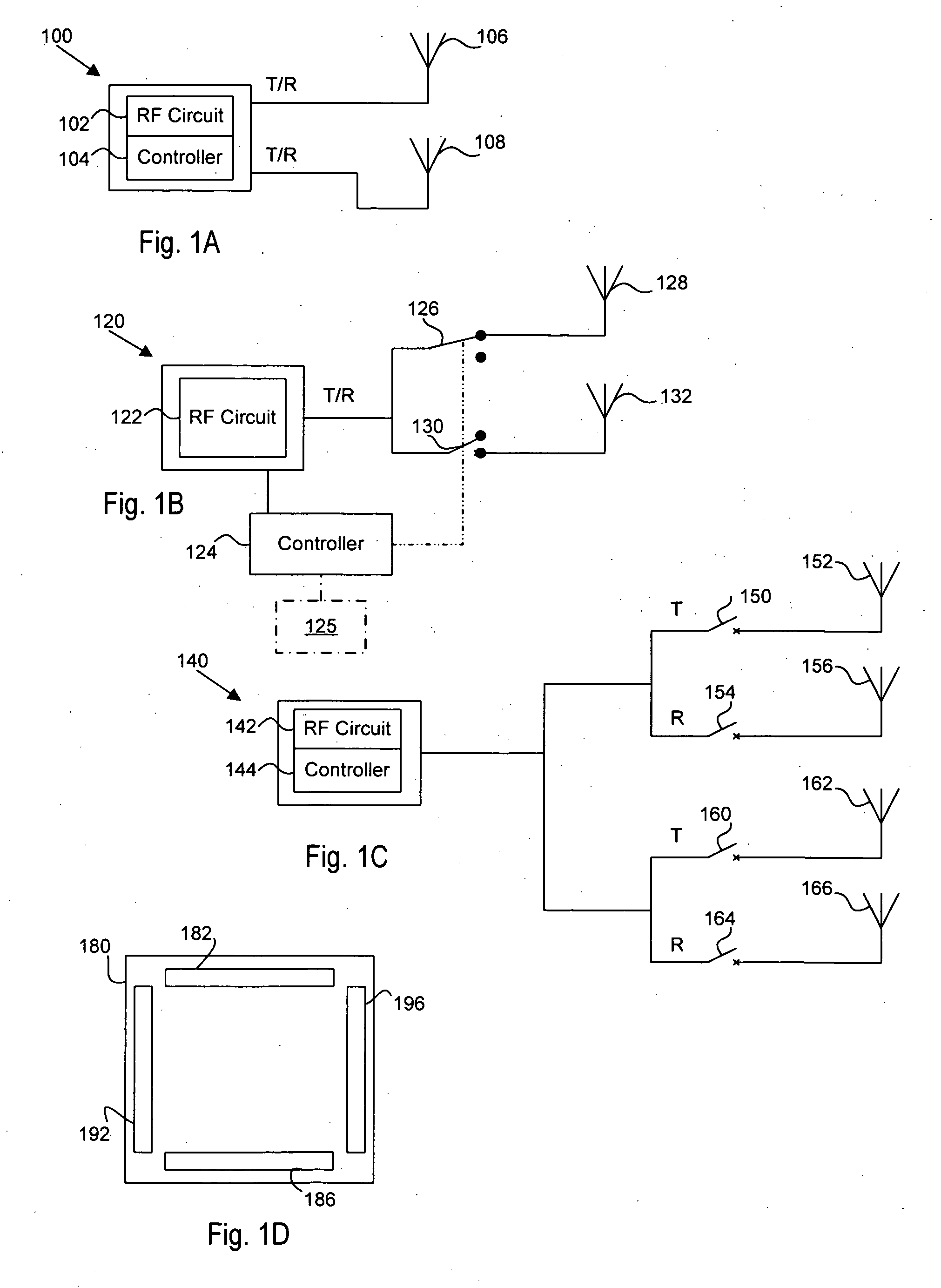
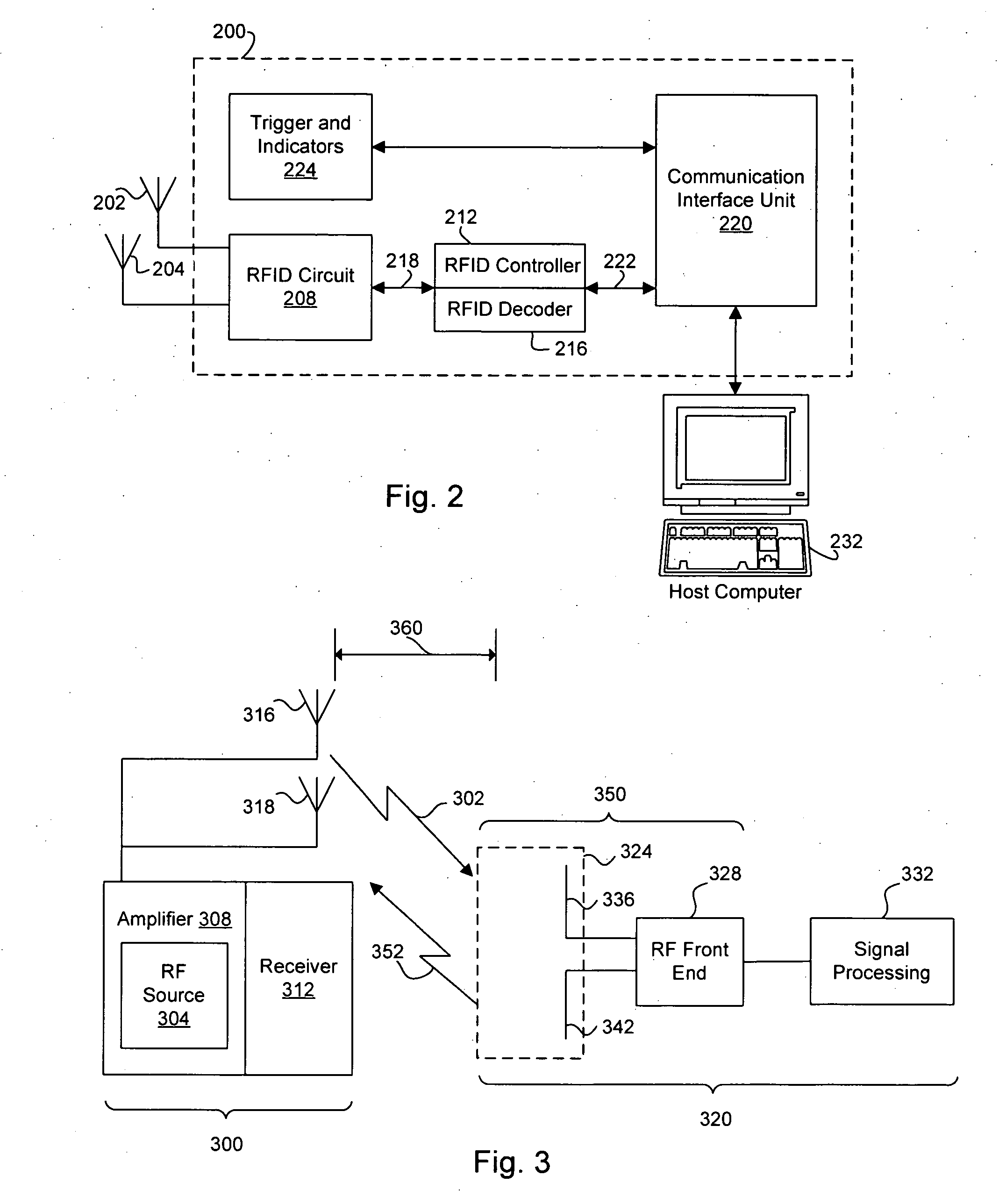
[0020] The embodiments of this disclosure will be best understood by reference to the drawings, wherein like parts are designated by like numerals throughout. It will be readily understood that the components of the embodiments as generally described and illustrated in the figures herein could be arranged and designed in a wide variety of different configurations. Thus, the following more detailed description of various embodiments, as represented in the figures, is not intended to limit the scope of the invention, as claimed, but is merely representative of various embodiments, each of which may differ in a variety of ways. While the various aspects of the embodiments are presented in drawings, the drawings are not necessarily drawn to scale unless specifically indicated. In addition, the steps of a method do not necessarily need to be executed in any specific order, or even sequentially, nor need the steps be executed only once, unless otherwise specified.

[0021] The phrases “conn...


PUM


Abstract

Radio Frequency Identification (RFID) antennas systems and methods that are less sensitive to orientation. One example includes an interrogator having a radio frequency transceiver, a first linearly polarized antenna in electrical communication with the transceiver, and a second linearly polarized antenna in electrical communication with the transceiver, the second antenna having a polarization in a direction substantially perpendicular to the first antenna; a control circuit is in electrical communication with the transceiver and with the first and second antennas, the control circuit operable to switch between interrogating with the first antenna and interrogating with the second antenna, and an RFID decoder is coupled to an output of the transceiver to decode an interrogated electromagnetic signal from a tag.

Description

RELATED APPLICATION DATA [0001] This application is a continuation-in-part of U.S. application Ser. No. 11 / 067,071, entitled “Orientation Insensitive Mobile RFID Antenna System,” filed Feb. 25, 2005, which is incorporated by reference herein in its entirety.BACKGROUND [0002] The present disclosure relates generally to wireless identification systems and methods, and more specifically, but not exclusively, to a radio frequency identification (RFID) system that employs alternate control of non-parallel antennas to make tag identification orientation less sensitive. [0003] Electromagnetic tag readers have been developed in the art to electronically sense the identification of an electromagnetically coupled tag over varying distances. RFID transponders are examples of such tags, which are operated in conjunction with RFID readers (or “interrogators”) for a variety of purposes, to include inventory control and data collection. An item having a tag associated with it is brought into a rea...

Claims


Application Information

Patent Timeline
IPC IPC(8): G08B13/14
CPCG06K7/10346H01Q21/24H01Q3/24H01Q1/2216
Inventor WAGNER, JAMES D.COHEN, MARK R.MCALLISTER, CLARKE W.
Owner DATALOGIC MOBILE
Why Eureka
Try Eureka