Display

a technology of display and contrast ratio, applied in the field of display, can solve the problems of deteriorating display quality, difficult production, inferior display performance of device observed in the oblique direction, etc., and achieve the effect of improving the viewing angle dependency of contrast ratio, deteriorating display quality, and improving display quality

Active Publication Date: 2007-08-23
SHARP KK +1
View PDF3 Cites 10 Cited by
  • Summary
  • Abstract
  • Description
  • Claims
  • Application Information

AI Technical Summary

Benefits of technology

[0017]The present invention has been made of the above-mentioned state of the art. The present invention has an object to provide a display which can improve viewing angle dependency of a contrast ratio at least in a specific azimuth without design change of a basic structure of a display element, limitation to white display state or black display state, and deterioration in display quality in other directions.

Problems solved by technology

It is generally known that these display performances when the device is observed in the oblique direction are inferior to those when observed in the front direction.
As a result, the production becomes difficult, and the production costs increase.
Further, its effect of improving the viewing angle dependency is insufficient.
Also in the optical compensation method using a retardation film, its effect of improving the viewing angle dependency is limited.
For example, an optimal phase difference value for compensating a phase difference of a liquid crystal cell varies between the cases of displaying white and black, and therefore it is impossible to compensate the phase difference of the liquid crystal cell in both black display and white display by the optical compensation method.
However, a method of obtaining the collimated light simply and effectively has not been established yet, and therefore, a method of using a scattering film for improving the viewing angle dependency is employed actually in combination with the diffusion backlight system, as mentioned above.

Method used


Image

  • Display
  • Display
  • Display

Examples


embodiment 2

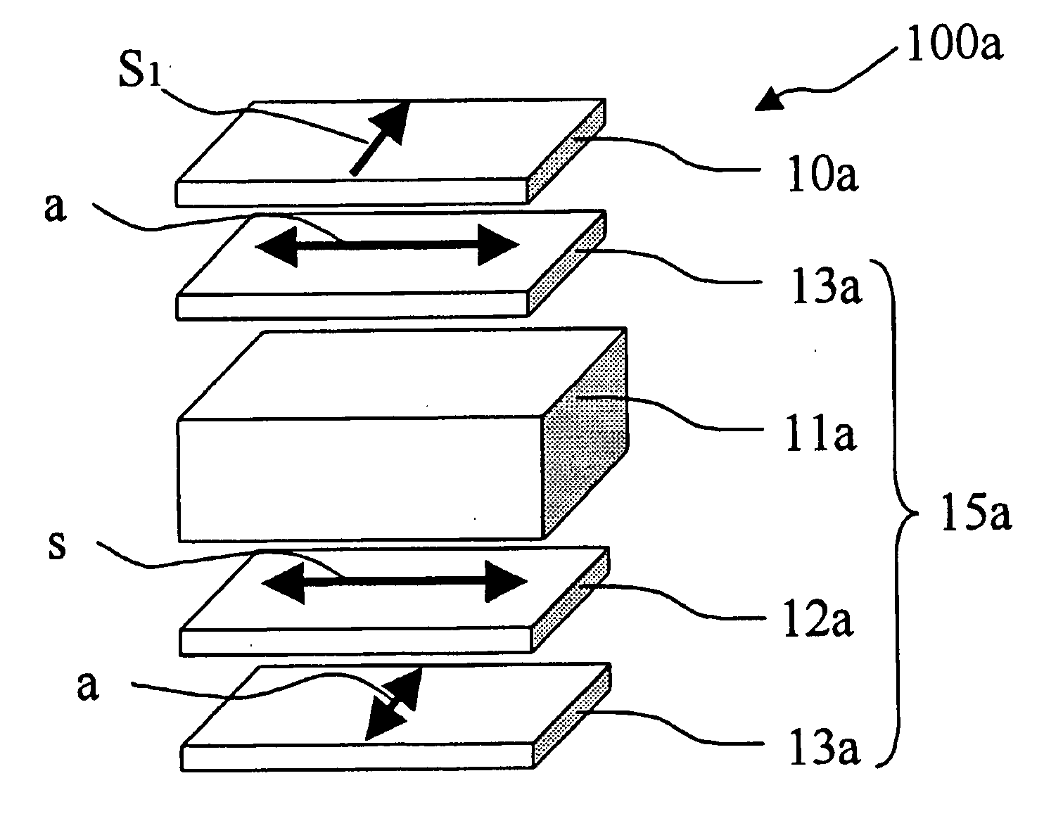
[0265]FIG. 9 is a perspective view schematically showing a configuration of a VA mode liquid crystal display 100a according to Embodiment 2 of the present invention. The attachment and relative positional relationship of axial directions between films is shown in FIG. 9 and Table 2.

TABLE 2ComponentAzimuth angle φFirst anisotropic scattering film 10a90°(axial azimuth S1 of scattering central axis)Polarizing element 3a on viewing screen side 0°–180°(absorption axis a)The second retardation film 12b (lagging axis90°–270°VA mode liquid crystal cell 11a45°, 135°, 225°, 315°(liquid crystal molecule tilt azimuth)Third retaradation film 12c (lagging axis s) 0°–180°Polarizing element 3a on back surface side90°–270°(absorption axis a)

(Preparation of VA Mode Liquid Crystal Display Element 15a)

[0266]First, a second polarizing plate 13b including a second retardation film 12b as a supporting film on the VA mode liquid crystal cell 11a side was attached to the viewing screen side of the liquid cr...

embodiment 3

[0270]FIG. 10 is a perspective view schematically showing a configuration of a VA mode liquid crystal display 100a according to Embodiment 3 of the present invention. The attachment and relative positional relationship of axial directions between films is shown in FIG. 10 and Table 3.

TABLE 3ComponentAzimuth angle φFirst anisotropic scattering film 10a90°(axial azimuth S1 of scattering central axis)First polarizing plate 13a on viewing screen0°–180°side (absorption axis a)VA mode liquid crystal cell 11a (liquid45°, 135°, 225°, 315°crystal molecule tilt azimuth)Fourth retardation film 12d (lagging axis s)0°–180°First polarizing plate 13a on back surface90°–270° side (absorption axis a)

(Preparation of VA Mode Liquid Crystal Display Element 15a)

[0271]First, a fourth retardation film 12d was attached to the backlight side of the VA mode liquid crystal cell 11a prepared in Embodiment 1. Further, the first polarizing plate 13a including a TAC film as a supporting film on the liquid crystal...

embodiment 4

[0275]FIG. 11 is a perspective view schematically showing a configuration of a VA mode liquid crystal display 100a according to Embodiment 4 of the present invention. The attachment and relative positional relationship of axial directions between films is shown in FIG. 11 and Table 4.

TABLE 4ComponentAzimuth angle φFirst anisotropic scattering film 10a90°(axial azimuth S1 of scattering central axis)Polarizing element 3a on viewing screen side 0°–180°(absorption axis a)Fifth retardation film 12e (lagging axis s)90°–270°VA mode liquid crystal cell 11a45°, 135°, 225°, 315°(liquid crystal molecule tilt azimuth)Sixth retardation film 12f (lagging axis s) 0°–180°Polarizing element 3a on back surface side90°–270°(absorption axis a)

(Preparation of VA Mode Liquid Crystal Display Element 15a)

[0276]First, a fifth polarizing plate 13e including a fifth retardation film 12e as a supporting film on the VA mode liquid crystal cell 11a side was attached to the viewing screen side of the liquid cryst...


PUM

PropertyMeasurementUnit
incidence angleaaaaaaaaaa
azimuth angleaaaaaaaaaa

Abstract

To provide a display which can improve viewing angle dependency of a contrast ratio at least in a specific azimuth without design change of a basic structure of a display element, limitation to white display state or black display state, and deterioration in display quality in other directions. The above-mentioned display is a display comprising: a display element with a contrast ratio dependent on a viewing angle; and an anisotropic scattering film having an anisotropic scattering layer, wherein the anisotropic scattering film is located on a viewing screen side of the display element and has a scattering central axis in substantially the same azimuth as an azimuth in which a contrast ratio of the display element in a direction inclined by a certain angle from a normal direction of a viewing screen of the display element has an extreme value.

Description

CROSS-REFERENCE TO RELATED APPLICATION[0001]This Nonprovisional application claims priority under 35 U.S.C §119(a) on Patent Application No. 2006-41456 and Patent Application No. 2006-41457 filed in Japan on Feb. 17, 2006, Patent Application No. 2007-15240 and Patent Application No. 2007-15241 filed in Japan on Jan. 25, 2007, the entire contents of which are hereby incorporated by reference.BACKGROUND OF THE INVENTION[0002]1. Field of the Invention[0003]The present invention relates to a display. More specifically, the present invention relates to a display including a display element such as a liquid crystal display element and an anisotropic scattering film.[0004]2. Description of the Related Art[0005]Liquid crystal displays typified by those in Twisted nematic (TN) mode have been known as a typical example of displays with display performances dependent on a viewing angle (with viewing angle characteristics). The term “with display performances dependent on a viewing angle” means...

Claims


Application Information

Patent Timeline
Patent Type & Authority Applications(United States)
IPC IPC(8): G02F1/1335
CPCG02F1/133504G02B5/0236G02B5/0257G02B5/02G02F1/13363
Inventor HASEGAWA, MASAHIROSAKAI, AKIRAHIGASHI, KENSAKUMOTODA, YASUHIKOKATAGIRI, HIROTO
Owner SHARP KK
Why Eureka
Try Eureka