Spread-spectrum receiver with fast m-sequence transform

Inactive Publication Date: 2007-08-23
COMTECH MOBILE DATACOM CORP
View PDF24 Cites 3 Cited by
  • Summary
  • Abstract
  • Description
  • Claims
  • Application Information

AI Technical Summary

Benefits of technology

[0008] It would be advantageous to provide a receiving system that is configured to distinguish among transmissions from a plurality of transmitters that are each communicating independently at a common frequency and using a common DSSS code sequence. It would also be advantageous to provide a receiving system that distinguishes among these transmissions as the frequency and transmission rates vary among the plurality of transmitters. It would also be advantageous to provide a receiving system that does not require that each transmitter include a receiver for achieving coarse synchronization with the receiver. It would also be advantageous to provide a receiving system that does not require a separate phase-locked loop for each transmitter.
[0009] These objects and others are achieved by providing a receiving system that dynamically searches the communications band for transm

Problems solved by technology

The modulated signal is spread across a bandwidth that is substantially larger than the bandwidth of the infor

Method used


Image

  • Spread-spectrum receiver with fast m-sequence transform
  • Spread-spectrum receiver with fast m-sequence transform
  • Spread-spectrum receiver with fast m-sequence transform

Examples


Embodiment Construction

[0018] In the following description, for purposes of explanation rather than limitation, specific details are set forth such as the particular architecture, interfaces, techniques, etc., in order to provide a thorough understanding of the concepts of the invention. However, it will be apparent to those skilled in the art that the present invention may be practiced in other embodiments, which depart from these specific details. In like manner, the text of this description is directed to the example embodiments as illustrated in the Figures, and is not intended to limit the claimed invention beyond the limits expressly included in the claims. For purposes of simplicity and clarity, detailed descriptions of well-known devices, circuits, and methods are omitted so as not to obscure the description of the present invention with unnecessary detail.

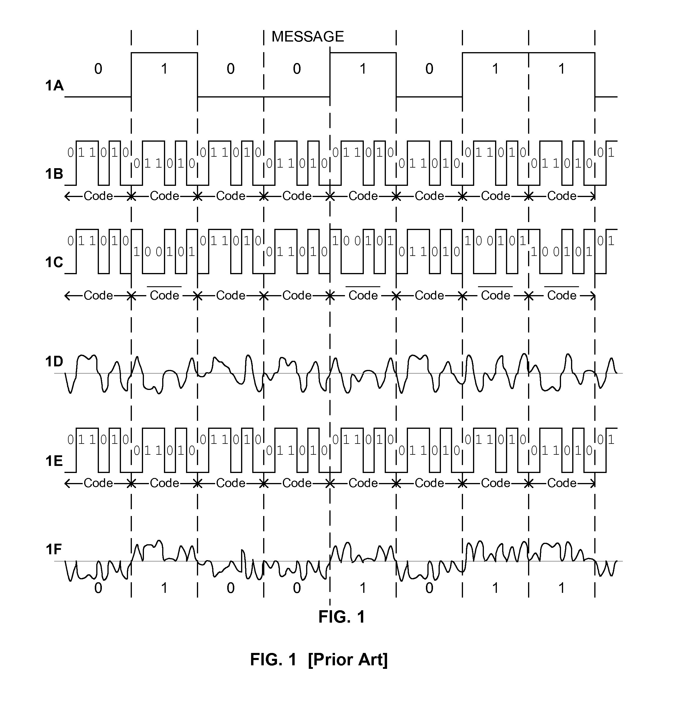
[0019]FIG. 1 illustrates an example timing diagram for an encoding and decoding process using an example spreading-code. Illustrated at 1A is ...


PUM


Abstract

A receiving system dynamically searches a communications band for transmissions of messages having the same nominal communications parameters, including the use of the same spreading code, but having potentially different specific frequencies and code-phases. The receiver samples the communications band at each code-phase of the spreading code over a span of down-converted transmission frequencies. When a message element is detected at a particular code-phase and frequency, it is forwarded to a demodulator that demodulates the message and sends it to its intended destination. This technique allows each transmitter to be independent of the receiver. In a preferred embodiment of this invention, a Fast M-Sequence Transform (a Walsh-Hadamard Transform) is used to determine the power level at multiple code-phases at a given frequency in parallel, thereby substantially reducing the time required to search for transmissions at each discrete code-phase.

Description

[0001] This is a continuation-in-part of U.S. patent application Ser. No. 10 / 208,882, filed 31 Jul. 2002, which is a continuation-in-part of U.S. Pat. No. 6,985,512, filed 28 Feb. 2000 and issued 10 Jan. 2006, each of which are incorporated by reference herein. This application also claims the benefit of U.S. Provisional Patent application 60 / 779,524, and 60 / 779,525, filed 6 Mar. 2006.BACKGROUND AND SUMMARY OF THE INVENTION [0002] This invention relates to the field of communications, and in particular to the processing of multiple asynchronous spread-spectrum communications. [0003] The Spread-Spectrum techniques are used to modulate an information signal such that the modulated signal appears as noise. The information is modulated by a pseudo-random signal, and can be demodulated, or despread, by the same pseudo-random sequence. This modulation is commonly referred to as Direct-Sequence Spread Spectrum (DSSS). The modulated signal is spread across a bandwidth that is substantially ...

Claims


Application Information

Patent Timeline
IPC IPC(8): H04B1/00
CPCH04B2001/70935H04B1/7093
Inventor STAFFORD, JAMES F.MCDERMOTT, SCOTT A.SENG, WILLIAM F.
Owner COMTECH MOBILE DATACOM CORP
Why Eureka
Try Eureka