Heated Floor Element having a Surface Layer

a surface layer and floor element technology, applied in the field of floor elements, can solve the problems of difficult transportation unsuitable for multiple uses, etc., and achieve the effects of high young's modulus, high stability of the floor element, and high stability

a surface layer and floor element technology, applied in the field of floor elements, can solve the problems of difficult transportation unsuitable for multiple uses, etc., and achieve the effects of high young's modulus, high stability of the floor element, and high stability

US20070196614A1Inactive Publication Date: 2007-08-23KELLNER PETER

Image

  • Heated Floor Element having a Surface Layer
  • Heated Floor Element having a Surface Layer
  • Heated Floor Element having a Surface Layer

Examples


Embodiment Construction

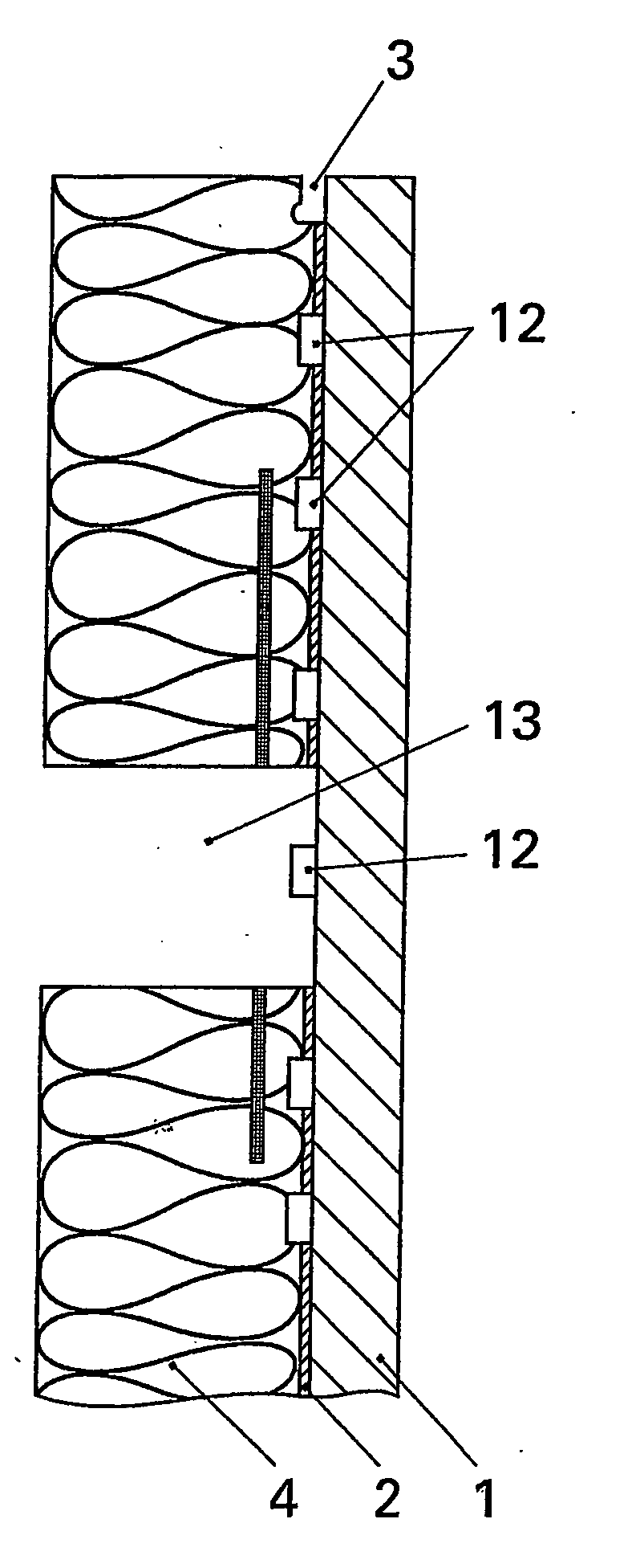
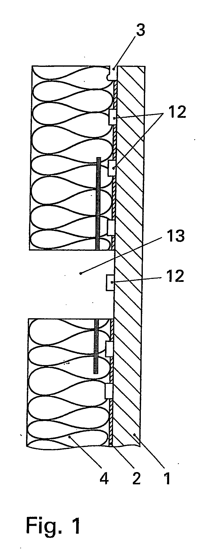
[0029] The cross section through a multilayer plate in accordance with the invention depicted in FIG. 1 shows a thin panel 1 of natural stone, at whose bottom a CFRP fabric of small thickness is two-dimensionally glued as a two-dimensionally extended reinforcement 2 by means of an epoxy resin. The thin panel 1 can also consist of glass, wood, metal or another stable material. The CFRP fabric exhibits a high Young's modulus in relation to the natural stone panel; the tensile strength and the compression strength of the CFRP fabric is essentially larger than the compression strength of the natural stone. Below the CFRP fabric a pressure resistant foam layer of expanded polypropylene is two-dimensionally glued. By the shown multilayer construction a high tensile bending strength is achieved at a low weight of the multilayer plate. An advisable embodiment provides for that the reinforcement 2 is arranged within the lightweight material layer 4. Reinforcement elements can be advantageous...


PUM

PropertyMeasurementUnit
depthaaaaaaaaaa
lengthaaaaaaaaaa
thicknessaaaaaaaaaa

Abstract

The invention relates to a floor element which is light-weight and easily transported, easily removed and therefore usable several times, is pleasant to walk on and can be used together with a floor heating system. The planar element for floors comprises a multilayer flag on the upper face of which a thin pressure-proof and abrasion-resistant flag, especially a natural stone flag, is disposed and on the lower face of which a pressure-proof light-density layer, fastened thereto by an adhesive glue, is disposed. Grooves are arranged in the vertical marginal areas of the light-density layer and connecting elements can be fixed in said grooves for connecting adjacent multilayer flags. According to the invention, the light-density layer consists of an expanded polypropylene foam.

Description

BACKGROUND OF THE INVENTION [0001] The invention relates to a plane element for floors, comprising a multilayer plate having a thin pressure and abrasion resistant panel arranged at its top side, the panel in particular consisting of natural stone, and below this panel a pressure resistant lightweight material layer fixated by an adhesive connection, wherein grooves are arranged in vertical edge surfaces and connection ledges are arrangeable in said grooves for connecting adjacently layed multilayer plates. [0002] The invention is designed, in particular, for removable and thus multiply reusable floors. With removable and multiply reusable floors that are needed, for example, for exhibitions it has been impossible to construct plane, high-quality floor areas having a high resilience hitherto, in particular using thin and thus lightweight natural stone panels. Permanently laying is also possible, of course. Additionally, floor heatings can be used efficiently in all cases. [0003] In ...

Claims


Application Information

Patent Timeline
23 Aug 2007
Publication
US20070196614A1
IPC
B32B3/16; E04F15/02; E04F15/08
CPC
E04F15/02; E04F15/02005; Y10T428/166; E04F2201/0511; E04F2201/0517; E04F15/08; E04F15/02016; E04F15/185
Inventors
KELLNER, PETER